20
Weather Sensor Battery Replacement
Specications
21
Specications
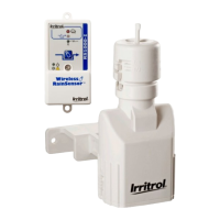
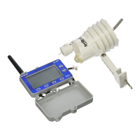
Weather Sensor/Transmitter
•2.75”Wx5”Hx6.25”D(overbracket)
7cmWx12.7cmHx15.9cmD(overbracket)
•Battery:9V-Alkaline,upto5-yearduration
•AntennaWire:
1.5” L x 0.192 Dia.
3.81 cm L x 4.8 mm Dia.
•RFReceptionRange:Upto1000’(304m)LOS
•OperatingTemperature:14–140°F(-10°–60°C)
•RainSensingMethod:Industry-standard,hygro-
scopic, stacked-disc style w/adjustable threshold
•Quick-Clip
TM
Mounting Bracket: Rain gutter/solid-
surface mounting option w/vertical adjustment
and stainless steel hardware.
•VisibleRFTransmissionLED
•UL,FCCandICApproval
•FCCID:OF7WS9
•IC:3575A-WS9
Receiver Module
•CompatiblewithRemote-readyIrritrolandToro
ControllersandCLSeriesHandheldRemote
•InputPower(fromcontroller):5vDC
•LCDScreenDimensions:
2.5”Wx1.25”H
6.35cmWx3.18cmH
•LCDContrastAdjustment
•Dimensions:
3.25”H(5.375”w/antenna)x4.125”Wx0.75”D
8.26cmH(13.16cmw/antenna)x10.48cmWx
1.9 cm D
•Power/DateCable:
20” L x 0.16 Dia.
50.8 cm L x 4.1 mm Dia.
RJ14 connector
•Indoor/OutdoorInstallation
•Weather-resistantEnclosure(withcoverclosed)
•UL,FCCandICApproval
•FCCID:OF7CL9
•IC:3575A-CL9
Weather Sensor Battery Replacement
In normal operating conditions, the Weather Sensor’s single, 9V-Alakaline battery can provide service up
to ve years. A loss of signal will result from a weak battery condition. Replace the battery as follows:
• The battery is stored in the upper half of the
sensor housing. To access the battery, release
and remove the upper housing by twisting it
clockwise while holding the base stationary.
• Disconnectthebatterywireclip.Removethe
used battery and insert a fresh 9V-Alkaline
battery between the foam pad and housing.
Reconnect the battery wire clip.
• Toreassemblethesensorhousing,dressthe
antenna wire through the lower housing,
exiting the center hole in the bottom grid.
• Matethehalvessquarely,aligningthetrans-
lucent dome above the mounting bracket.
• Turntheupperhousingcounterclockwise
to lock into lower housing (held stationary).
Note: Proper disposal of all batteries is very im-
portant for the environment and must comply
with the battery manufacturer’s recommended
procedures.
 Loading...