6
Receiver Module Installation and Setup
Receiver Module Installation and Setup
7
4. The Receiver Module will automatically* synchronize time
and date with the host controller upon initial power-up.
* Note: Does not apply to TMC-212 controller.
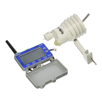
5. Verify that the time and date are synchronized correctly.
If necessary, adjust the Receiver Module as follows:
Note: The display will automatically return to the Home screen
if a key is not pressed within 60 seconds.
• PresstheMENU key to display the Main Menu screen.
(The CLOCK menu option is selected by default.)
• PresstheENTER key to display the Clock review screen.
• PresstheSETUP key to display the Set Clock screen.
Note: To download the current time and date from the control-
ler, press the GET key. When prompted, press the YES key. .
• Pressthe or key to adjust the selected (underscored)
value. Press the NEXT key to select the next value. Continue
setting the current day, year and time.
Note: To change the clock time display format, press the 12/24
key. To return to the previous screen without making changes,
press the CANCEL key.
• WhentheReceiverModuleandcontrolleraresynchronized
to the current time and date, press the SAVE key.
• PresstheEXIT key two times to return to the Home screen.
Climate Logic System Installation
Receiver Module Installation and Setup
Note: Installation methods must comply with all applicable national and local building codes.
1. Setup controller watering Program A to provide an irrigation baseline for the Climate Logic system.
The station run time, cycle start time(s), and watering day schedule* must be congured for the
hottest/driest conditions expected, without causing over-watering and runo. Retain all watering
time/day restrictions in the program schedule as required.
Note: By default, Climate Logic modies the run time of stations assigned only to Program A. To include
Program B, or Programs B and C, see page 13.
*Note: For TMC-212 controller only: Inter-
val day scheduling is not compatible with
Climate Logic. Calendar and Odd/Even
schedules are not aected.
2. Route the connection cable into the con-
troller cabinet. Insert the cable connector
into the controller’s remote control jack.
Note: Use the provided CMR-ADP cable
adapter assembly for KwikDial and MC-E
(Blue) controller applications.
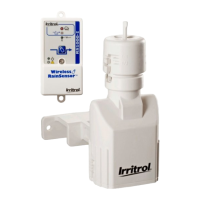
3. Secure the Receiver Module to the wall
next to the controller using the provided
screws or other suitable fasteners.
Note: For indoor application, adhesive-
backed hook and loop tape (not included)
can be used instead of screws.
EARTH
GROUND
MV/
Pump
Sensor
+
-
7 8 9 10 11 12
1 2 3 4 5 6
24 VAC
VC
MENU
_ _ _
F 100%
CLIMATE LOGIC
9:15a
11/16
MV/
PUMP
1 2 3 4 5 6 7 8 9 10 11 12
MV/
PUMP
24VAC
RAIN
SENSOR
REMOTE
GND
1 2 3 4 5 6 7 8 9 10 11 12
VC/
COM
VC/
COM
13 14 15 16 17 18 19
VC/
COM
37 38 39 40 41 42 43
37 38 39 40 41 42 43
25 26 27 28 29 30 31 32 33 34 35 36
25 26 27 28 29 30 31 32 33 34 35 36
VC/
COM
VC/
COM
VC/
COM
VC/
COM
13 14 15 16 17 18 19
VC/
COM
MV/
PUMP
1 2 3 4 5 6 7 8 9 10 11 12
MV/
PUMP
24VAC
RAIN
SENSOR
REMOTE
GND
1 2 3 4 5 6 7 8 9 10 11 12
VC/
COM
VC/
COM
13 14 15 16 17 18 19
VC/
COM
37 38 39 40 41 42 43
37 38 39 40 41 42 43
25 26 27 28 29 30 31 32 33 34 35 36
25 26 27 28 29 30 31 32 33 34 35 36
VC/
COM
VC/
COM
VC/
COM
VC/
COM
13 14 15 16 17 18 19
VC/
COM
POSTHOT
Total Control-R
CMR-ADP
Blue Wire
(Up) to Pin 1
Rain Dial-R
KwikDial
 Loading...