7
Power Source Installation
WARNING: All electrical components and installation practices must meet applicable national and local electrical
codes including installation by a qualied personnel. These codes may require an external junction box mounted on the
cabinet and a circuit breaker in the main wiring having a contact separation of at least 0.120” in the line and neutral poles.
The 120 VAC power source must be turned OFF prior to servicing. The power cable used for connection to the controller
must have an insulation rating of 221° F minimum.
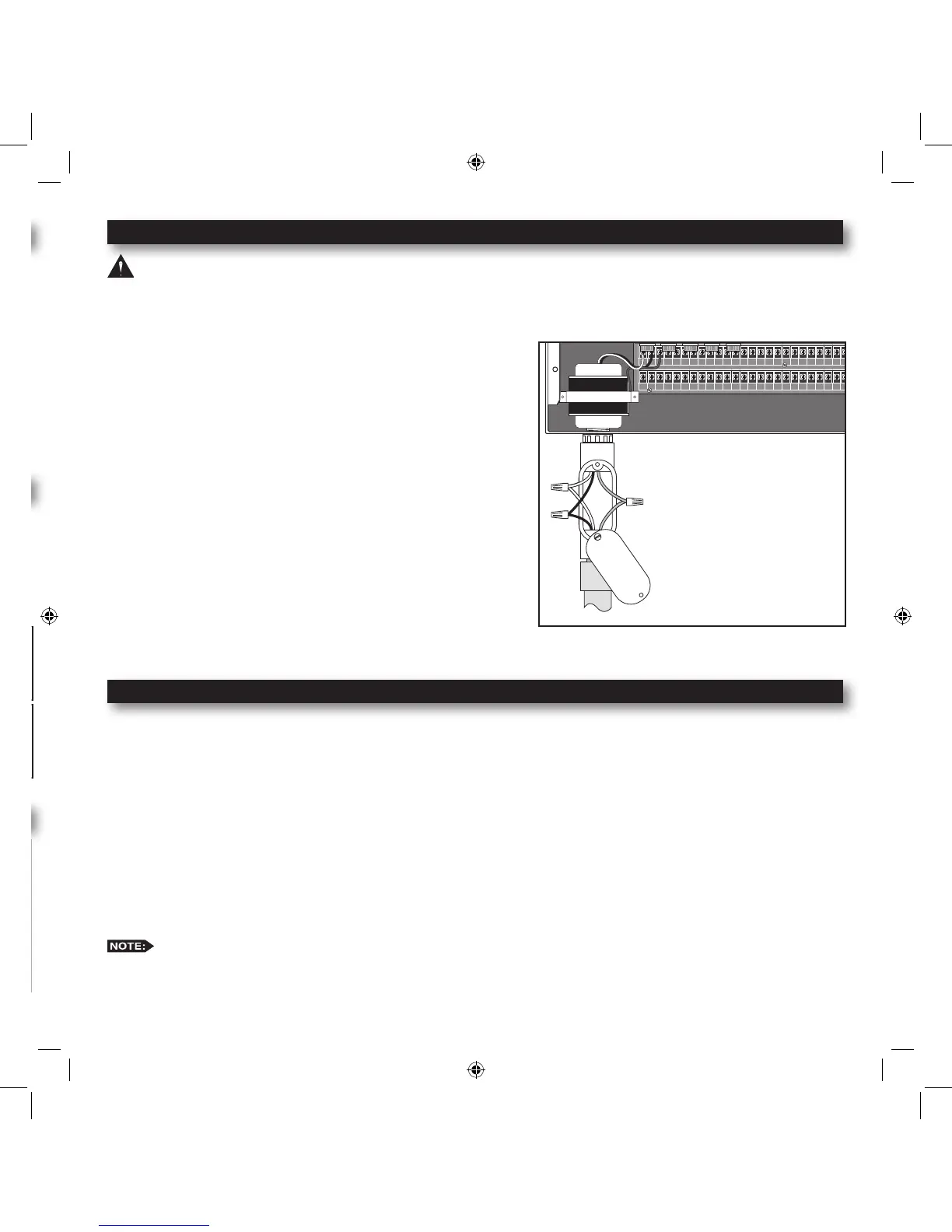
Step 1 – For power source connection, install a 1/2” electrical
conduit from the 120 VAC power source to the MC-E
controller cabinet.
Step 2 – Install an electrical junction box at the transformer to
allow access for future servicing.
Step 3 – Conrm that power has been disconnected at the power
source using a volt meter or voltage detector.
Step 4 – Route 14-AWG insulated solid copper wires for Power
(Black), Neutral (White) and Equipment Ground (Green)
through the conduit and into the junction box.
Step 5 – Strip back 3/8” of insulation from each wire. Using wire
connectors, connect the wires with similar colors together
(Black with Black, White with White, etc.).
Step 6 – Tuck the wires inside the junction box and replace the
cover.
Step 7 – Apply power to the controller.
Circuit Breaker Diagnostic System
The controller’s system for managing an electrical short circuit is designed to isolate the station with the problem and
continue to water operable stations. The sequence the controller follows is listed below.
1. The controller reaches a station with a short circuit.
2. The controller shuts off the problem station and skips to the next station in the same program and continues operation.
3. The controller displays “Fuse Alarm on __” and the problem station’s number as well as the other station in operation.
4. In between programs, when the controller is idle, it will display the Fuse Alarm station alternating with the display of
Day/Date/Time.
5. The next time the controller is supposed to run the station, it will try again. If the cause of the short has been repaired,
the Fuse Alarm will disappear from the display and the station will run normally. You can also use the CLEAR button
to clear the Fuse Alarm from the display. This does not x the shorted circuit, but only clears its display.
The controller has fractions of a second to detect and shutoff the problem station before the short circuit causes
damage. On occasion, with multiple programs and stations running, the controller shuts off and displays two stations as
having shorts. You can test each station in MANUAL mode or with STATION TEST to nd the shorted one.
Rain Sensor Installation (Purchased Separately)
IMPORTANT! The INHIBIT SENSOR is designed for a normally closed
rain sensor. The wire jumper must be present at the terminals if a sensor is not
connected.
Step 1 – Route the rain sensor cable into the controller terminals.
Step 2 – Remove the wire jumper from the INHIBIT and SENSOR terminals for
the 18 stations or more models and
INHIB.SEN and SEN.COM for the 12 stations or less models. Refer to
the provided rain sensor installation guide for wiring instructions and
connect accordingly.
The INHIBIT SENSOR will operate on any Function Dial position settings.
Start Sensor Installation (Purchased Separately)
IMPORTANT! The START SENSOR input is designed for a normally open
sensor and works in conjunction with Options 1 and 2. When the start sensor is
activated, the MC-E controller will immediately activate Program 1 providing
Option 2 is activated. Program 1 will continue to repeat the cycle until the start
sensor is deactivated. The activation of the start sensor will not affect any other
programs. Option 1 works similarly by turning ON program 8, however all other
programs are turned OFF.
Step 1 – Route the sensor connection cable through the bottom of the controller
cabinet and into the controller terminals.
Step 2 – Refer to the provided sensor installation guide for wiring instructions.
The START SENSOR will operate on any Function Dial
position except for RAIN OFF.
CLIMATE LOGIC
TM
Weather Sensor (Purchased Separately)
The CLIMATE LOGIC
TM
weather sensing system connects to the upper remote
port using the CMR-ADP adapter cable (black wire up). CLIMATE LOGIC
governs the MC-E Blue’s global water budget to make the entire controller
“follow the weather”.