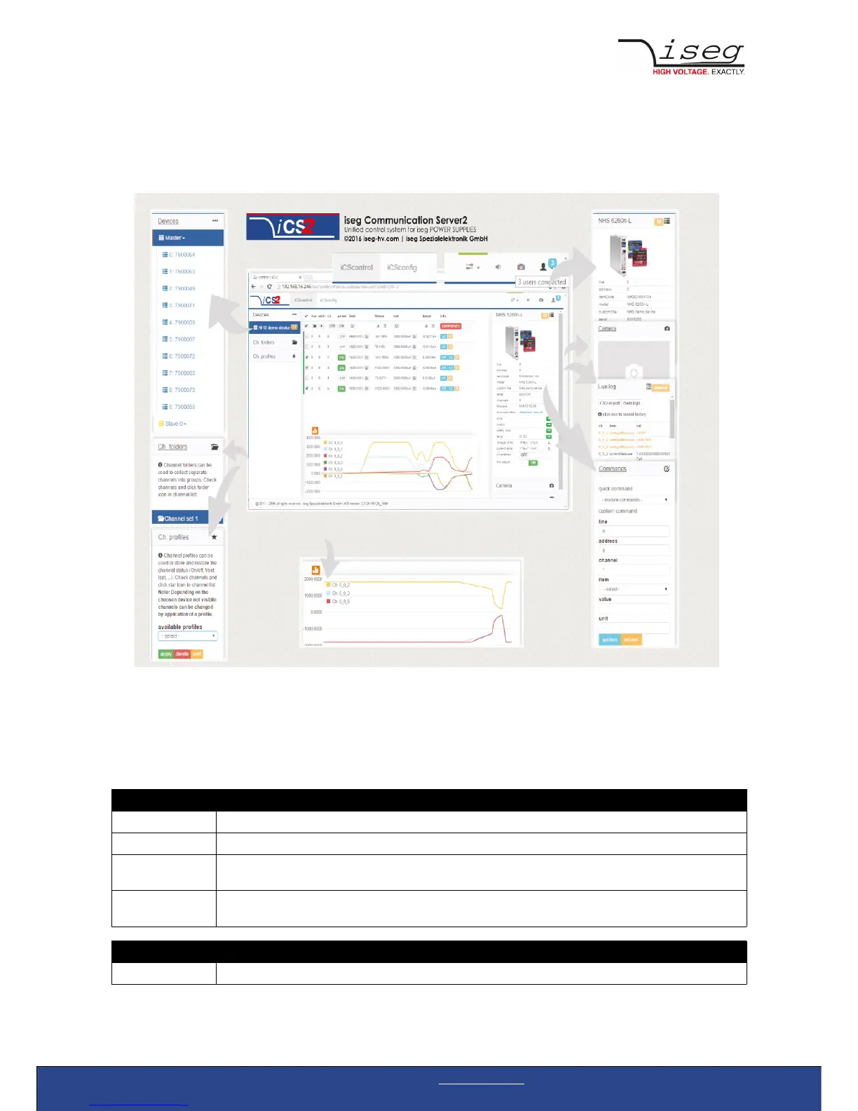
iCScontrol – control and monitor web application
The user interface of iCScontrol software is divided into three bars.
Left bar: Hardware Explorer
The left column shows the configured hardware.
If connected with iseg CAN line management slaves are shown in yellow or green background, corresponding to the CAN line they
are connected with. Every device has a colored left border showing the running state.
Crate/Device running states
grey one of the nested modules is ramping to the desired voltage
yellow one channel of one of the nested channels is ramping to the desired voltage
red the crate / device (or one of the nested modules/channels) has one or more errors (refer to the error/event
badges)
green the crate / device (and all of the nested modules) are in a good condition, at least one channel of a nested
module is running high voltage
Module running states
grey not present, not connected or switched off