ATTENTION
CAUTION
Do not connect both CAN connectors of a CC2x controller in any way, neither direct nor by building CAN
ring bus topology.
Connecting legacy crates (ECH238, 224 etc.)
CC2x controllers are able to connect legacy CAN-only driven iseg crates. So it is possible to extend existing hardware setups with a
new MMS series crate (ECH44A, ECH242, ECH244) and CC2x crate controller to access complete hardware by Ethernet or WiFi with
all major advantages of the integrated server hardware.
Legacy crates don't automatically configure their address. The address of the backplane (bank address) must be selected by a
rotary selector switch of the legacy's crate controller. Please note:
• Please pay attention that every legacy crate is configured to a unique address within a CAN line.
• Modules labeled with a six digit serial number allocate one or two addresses dependent on the serial number.
If there is one module in a legacy crate that's six digit serial number has a one at the last digit, only equal bank
addresses are allowed.
• Crate controllers of legacy crates must be configured to a CAN-Bitrate of 250 kBit/s
Each of the Master´s CAN-Lines can address up to 64 modules in legacy crates.
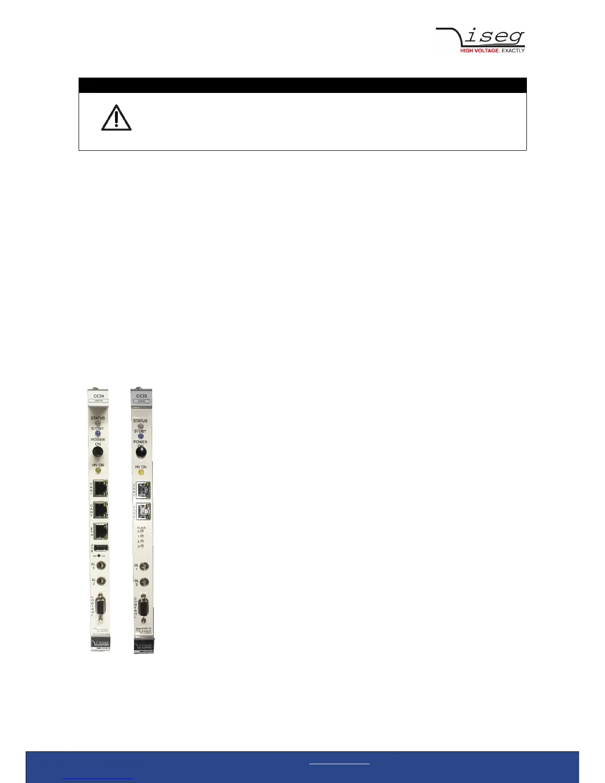
6 Front panel
LED STATUS System state:
• LED off: Crate is switched off / Standby mode
• LED green: Crate is running without error
• LED red: Error occurred (Crate Status bit Sum Error is set)
LED STDBY Standby mode:
• LED blue: Crate is connected to mains,
remote controllable, WiFi and Ethernet connections are active
Pushbutton POWER ON Switches the crate on or off by pressing the button for one
second
ON: All modules will be supplied with power by crate and can be
controlled
The fan speed is regulated according to the maximum
temperature within the crate
OFF: All modules will be switched off.
The fans run at minimal speed.
LED HV ON HIGH VOLTAGE is active
LED yellow: At least one channel in crate generates high voltage
or is measuring an output voltage of more than 60 Volt
CAN1 RJ-45 CAN – connector for slave controller connection
CAN2 RJ-45 CAN – connector for slave controller connection
ETH (CC24 only) RJ-45 Ethernet network connector (10/100/1000MBit)
USB (CC24 only) USB 2.0 connector, for external WiFi, camera, firmware upgrade,
flash memory
LED SLAVE 0-3 (CC23 only) Indicate the slave position in the yellow or green CAN line
SL 1 Safety-Loop-Connector 1
SL 2 Safety-Loop-Connector 2
CONTROL D-SUB-9 connector with configurable digital I/O