8
MCP-Z Process/Ismatec SA/14.07.00/CB/GP
Hinweis
Für die Benutzung der Analog- und
RS232-Schnittstelle unter IP-65
Bedingungen verweisen wir auf
Seite 51.
Please note
For using the analog or RS232
interface under IP-65 conditions
please refer to page 51.
Remarque
Pour l‘utilisation de l‘interface
analogique ou RS232 sous des
conditions IP-65: voir page 51.
4
3
1
52
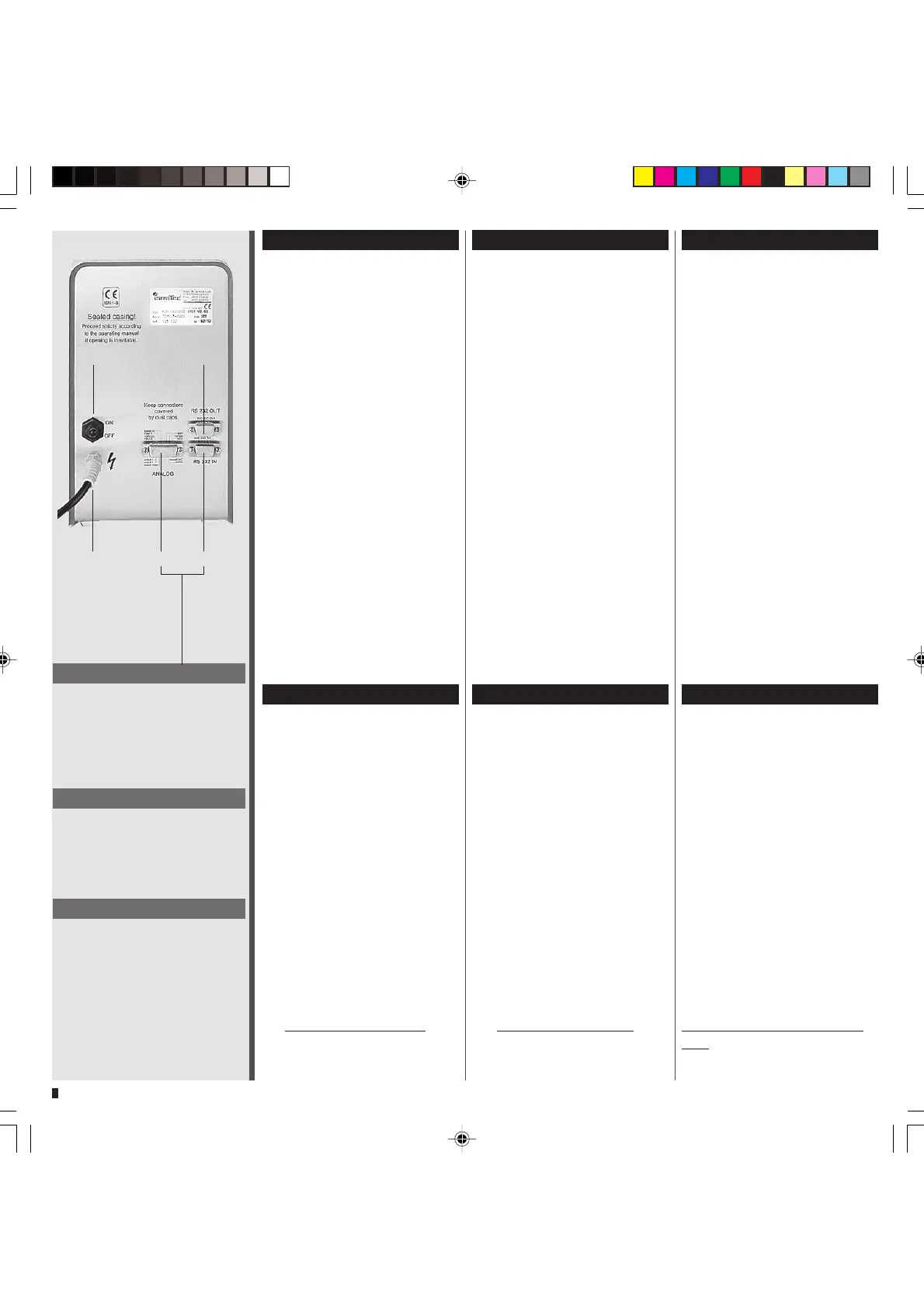
Geräterückwand
1 Netzschalter (ein/aus)
2 Netzkabel
3 RS232 IN (Eingang, weiblich)
4 RS232 OUT (Ausgang, männlich)
5 Analog-Schnittstelle
■
Eingänge für:
– Drehzahlsteuerung
0–5 V oder 0–10 V, bzw.
0–20 mA oder 4–20 mA
– Start/Stopp
– Fußschalter
– 2 digitale Eingänge (TTL-
Pegel)
■
Ausgänge für:
– Drehzahl 0–10 V
DC
oder 0–12 kHz
– 2 Universal-Ausgänge
z.B. für Ventileinheit
(Seite 30/49)
Netzspannung
85 – 264 VAC
47 – 60 Hz
ohne Umschaltung
Leistungsaufnahme
150 W max.
Absicherung Steuerprint*
1.6 A, flink
4.0 A, träge
Absicherung Netzteil*
4.0 A, träge
* Siehe auch Seite 51–53
Steckdose/Netzkabel
Die Steckdose muss geerdet sein.
(Schutzleiterkontakt)
Rear panel
1 Mains switch (on/off)
2 Power cord
3 RS232 IN (female)
4 RS232 OUT (male)
5 Analog interface
■
input for:
– speed control
0–5 V or 0–10 V, and
0–20 mA or 4–20mA
– Run/Stop
– Foot switch
– 2 digital inputs (TTL-level)
■
output for:
– speed 0–10 V
DC
or 0–12 kHz
– 2 universal outputs
e.g. for valve unit
(pages 30 and 49)
Mains voltage
85 – 264 VAC
47 – 60 Hz
no adjustments necessary
Power consumption
150 W max.
Fuse rating on control board*
1.6 A, fast-blow
4.0 A, slow-blow
Fuse rating on power supply*
4.0 A, slow-blow
* See also pages 51 to 53
Socket/Power cord
The socket must be earthed.
(protective conductor contact)
Tableau arrière
1 Commutateur principal
2 Prise d’alimentation
3 RS232 IN (entrée femelle)
4 RS232 OUT (sortie mâle)
5 Interface analogique
■
Entrée:
– Commande de vitesse
0–5 V ou 0–10 V, resp.
0–20 mA ou 4–20mA
– Marche/arrêt
– Pédale de commande
–2 entrées numériques
(TTL-level)
■
Sortie:
– vitesse 0–10 V
DC
ou 0–12 kHz
– 2 sorties universelles
p. ex. pour l'unité de valve
(pages 30 et 49)
Tension d‘alimentation
85 – 264 VAC
47 – 60 Hz
sans commutation
Consommation de courant
150 W max.
Type de fusibles
carte de comande*
1.6 A, à action rapide
4.0 A, à action retardée
Type de fusibles
carte d'alimentation*
4.0 A, à action retardée
* Voir aussi pages 51–53
Prise/câble d’alimentation
La prise doit être raccordée à la
terre (contact conducteur de
protection).