DRIVEABILITY AND EMISSIONS 6E1-197
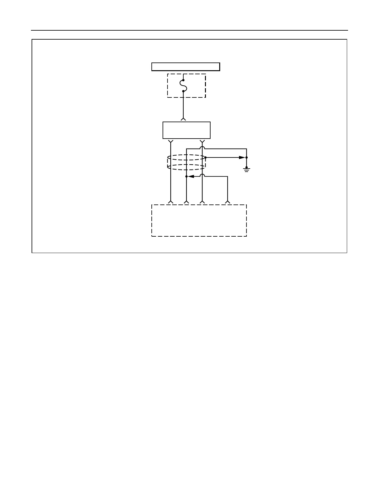
HOT IN START AND RUN
IG.
Coil
Fuse
15A
I/P
FUSE
BLOCK
2
W/G
Ignition
Coil
Ignition
Coil
1.25
G
1.25
L
Engine
Control
Module
(ECM)
E1 E4 E3
Electronic Spark
Timing Control
1.25
BLK
1.25
BLK
E2
1,4 2,3
DIAGNOSTIC TROUBLE CODE (DTC) (Flash DTC = 42)
IGNITION COIL DRIVER "A" SHORT TO BATTERY
Circuit Description
The ignition control circuit in ECM provides a zero volt
or a 5 volt signal to the ignition coil driver. The normal
circuit voltage is zero volts. When the module receives
the 5 volt signal from the ignition control circuit, it
provides a ground path for the B+ voltage supplied to
the ignition primary coil. When the ECM turns off the 5
volts to the module, the module will remove the
ground path of the ignition primary coils; causing the
magnetic field produces a voltage in the secondary
coils which fires the spark plug.
The circuit between the coil driver and the ignition
control circuit is monitored for a short to battery on the
Electronic Spark Timing A/coil driver A line. When the
ECM detects a problem in the ignition control circuit, it
will set DTC 42.
Conditions for Setting the DTC
• Fault feedback line generates an interrupt on start
of dwell.
• No Electronic Spark Timing requested by serial
data.
Action Taken When the DTC Sets
• The ECM will illuminate the malfunction indicator
lamp (MIL) the first time the fault is detected.
Conditions for Clearing the MIL/DTC
Once the ECM determines that a fault(s) has been
rectified then the CEL will switch OFF, although the
fault code will remain in the ECM memory.
Any fault codes will remain in ECM memory until -
1. They are cleared by disconnecting the Battery for
more than 30 seconds.
2. A service tool such as Tech 2 is used to clear them.
3. Ten consecutive starts without logging a fault.
Diagnostic Aids
Check for the following conditions:
• Poor connection at the ECM - Inspect the harness
connectors for backed-out terminals, improper
mating, broken locks, improperly formed or