REPAIR STANDARDS
216
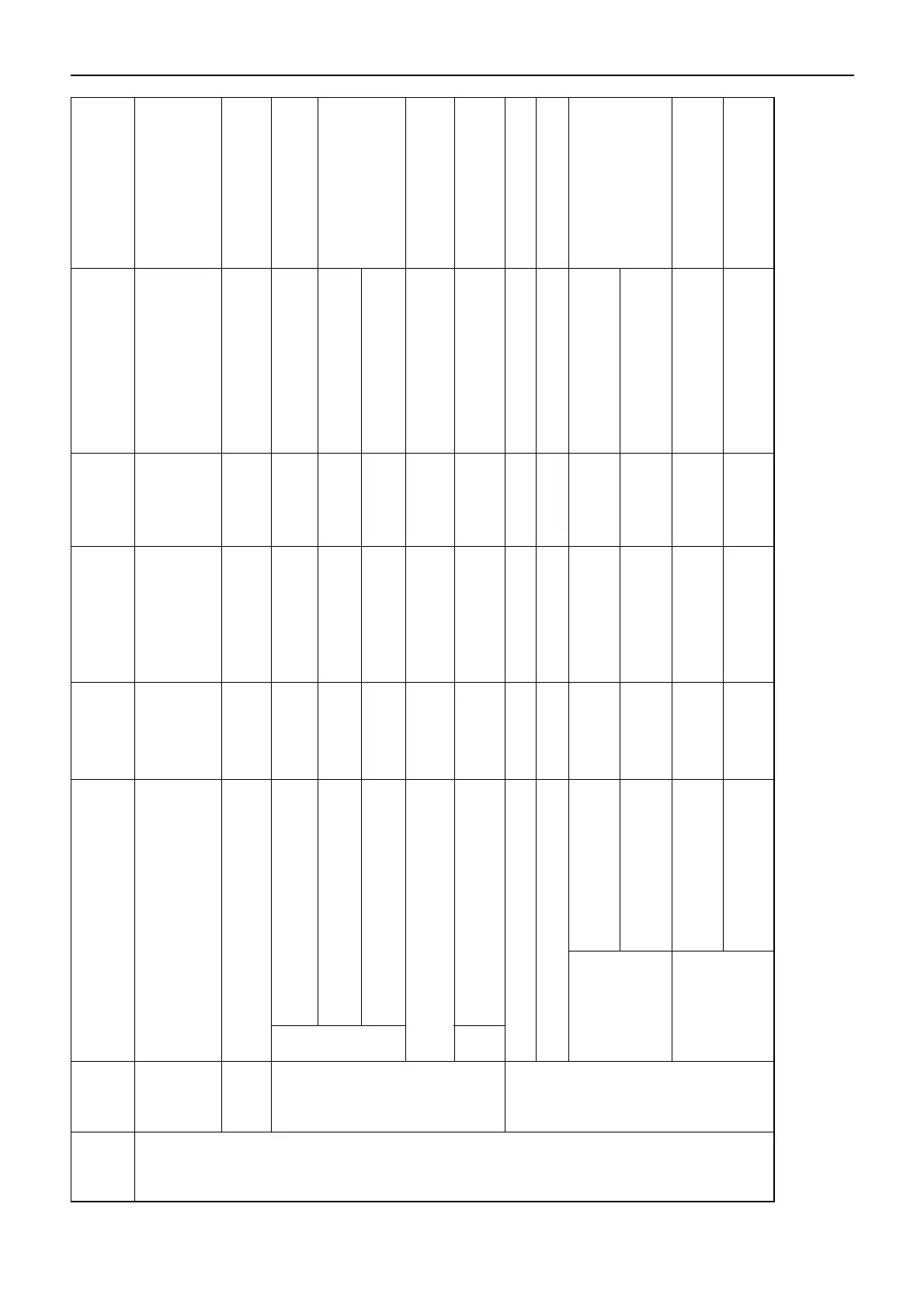
Major Name Nominal
Assembly
Category
of Part
Inspection Item
Dimension
Standard Limit Repair Procedure Comments
Value
If warning indicator lights
when engine is operating
Warning lamp indication
a
t
normal speeds, check
and repair electrical system.
Check for looseness, cuts or damaged
Repair
insulation to wiring.
Shaft runout
0.1 (0.0039)
Replace rotor
or ress
Bearing chatter Replace bearings
Rotate by handand check
for smooth rotation:
no abnormal sound or
Thrust side chatter 0.3 (0.012) Repair
resistance should be felt.
Slip ring dia waler
31.6 30.6
Replace
(1.24) (1.20)
Length
14.5 7.5
(0.57) (0.3)
Loose mount Repair
Brush length 15.0 (0.59) 9.0 (0.35) Replace
Jeries coil
—
Magnetic resistance (Ω) If coil resistance value
switch is severely abnormal,
(at 20°C [68°F])
Shut coil
0.27
replace switch.
resistance (Ω)
O.D.
Dia. 30.0 Dia. 29.0
Replace armature
Commutator
(1.18) (1.14)
Undercut depth
0.5 – 0.8 0.2
Repair
(0.02 – 0.03) (0.008)
Electrical
Charge/
Discharge
indication
Wiring
Alternator 12V, 35A
(Hitachi 1-81200-756-0)
Rotor
Brush
Starter 12V, 2.2 kW
(Hitachi 8-97084-879-0)
 Loading...


