EasyManua.ls Logo

ITC T-6350 User Manual

ITC T-6350
15 pages
To Next Page IconTo Next Page
Page #1 background imageLoading...
Page #1 background image
350/500/650-WATT AMPLIFIER
T-6500
T-6350
T-6650
OPERATION MANUAL
Please follow the instructions in this manual to obtain the optimum results from this unit.
We also recommend that you keep this manual handy for future reference.
PUBLIC ADDRESS SYSTEM
ON
OFF
POWER
CLIP
TEMP
VOLUME
PROT
5
0
1
2
3
4 6
7
8
9
10
SIGNAL
350-WATT AMPLIFIER
T-6350
ON
OFF
POWER
CLIP
TEMP
VOLUME
PROT
5
0
1
2
3
4 6
7
8
9
10
SIGNAL
500-WATT AMPLIFIER
T-6500
ON
OFF
POWER
CLIP
TEMP
VOLUME
PROT
5
0
1
2
3
4 6
7
8
9
10
SIGNAL
650-WATT AMPLIFIER
T-6650
Question and Answer IconNeed help?

Do you have a question about the ITC T-6350 and is the answer not in the manual?

ITC T-6350 Specifications

General IconGeneral
BrandITC
ModelT-6350
CategoryAmplifier
LanguageEnglish

Summary

Safety Precautions

Safety Symbol and Message Conventions

Explains warning symbols and messages used to prevent injury and property damage.

Installation Safety Guidelines

Precautions for installing the unit, including avoiding water, using correct voltage, and grounding.

Operational Safety Guidelines

Precautions during unit use, covering issues like smoke, water ingress, and opening the case.

General Description

Features

Nomenclature and Functions

Front Panel Controls and Indicators

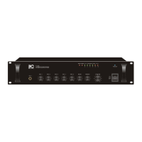
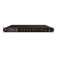
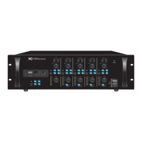
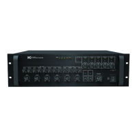
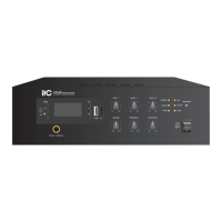
Identifies and describes the front panel components like power switch, volume, and various indicators.

Rear Panel Connections and Features

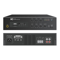
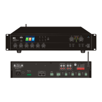
Details the rear panel connections including speaker outputs, line inputs, and ground lifter.

Rear Panel (24V) Connections

Details the rear panel connections for the 24V version, including battery power interface.

Connections

Speaker Connections

Illustrates how to connect speakers using 70V/100V or 4-16 ohm terminals.

XLR and Phone Jack Connections

Explains the use of XLR and phone jack connectors for audio signal input.

Applications

Block Diagram

Specifications

Dimensional Diagram

Unit Dimensions

Provides detailed measurements for the unit's front, side, and depth.

Ventilation Clearance

Specifies required clearance around the unit to prevent overheating.

Related product manuals