Basic Operation
Level rise slope 10us
Level fall slope 2us
Minimum time width
for low level keep
30us
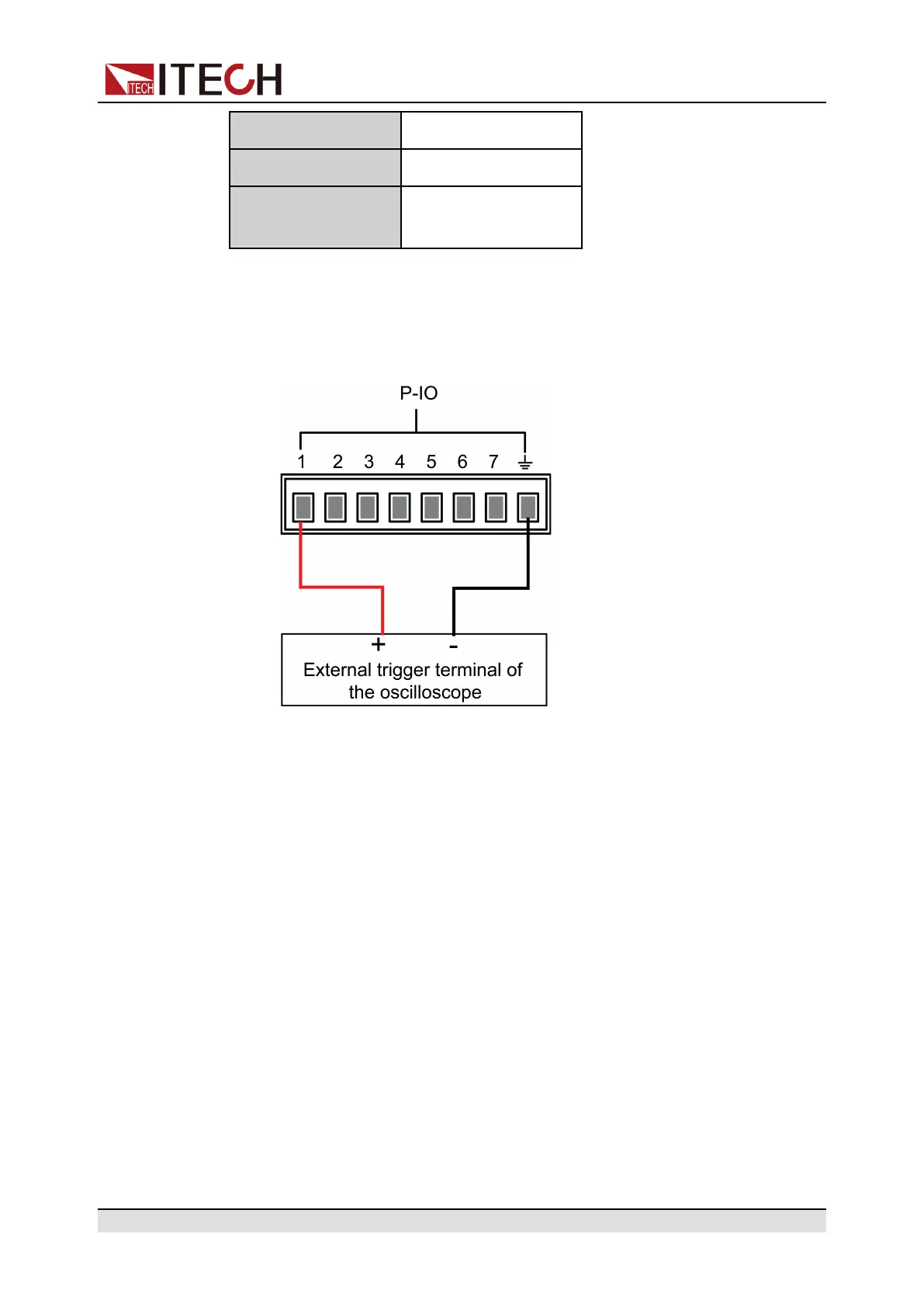
• Pulse input: When the instrument is under protection, the instrument will
clear protection after receiving the pulse signal from external input.
1. Refer to the figure below to connect pin 1 to the external oscilloscope.
2. Confirm that pin 1 function is set to the default option, namely
IO-1. Ps-Clear, Not-Invert.
3. Taking OCP as an example, set the protection point of OCP.
4. Build the test environment to enable the instrument to enter the OCP
state.
5. Send pulse signal to pin 1.
6. Check whether the protection state of this instrument is cleared.
• Pulse output: When the instrument’s protection state is released, and
[On/Off] is from Off to On, pin 1 will send a pulse signal to the external
instrument.
1. Clear the instrument’s OCP protection.
2. Check the oscilloscope and confirm whether pin 1 has pulse output.
Copyright © Itech Electronic Co., Ltd.
170