Power Supply Function
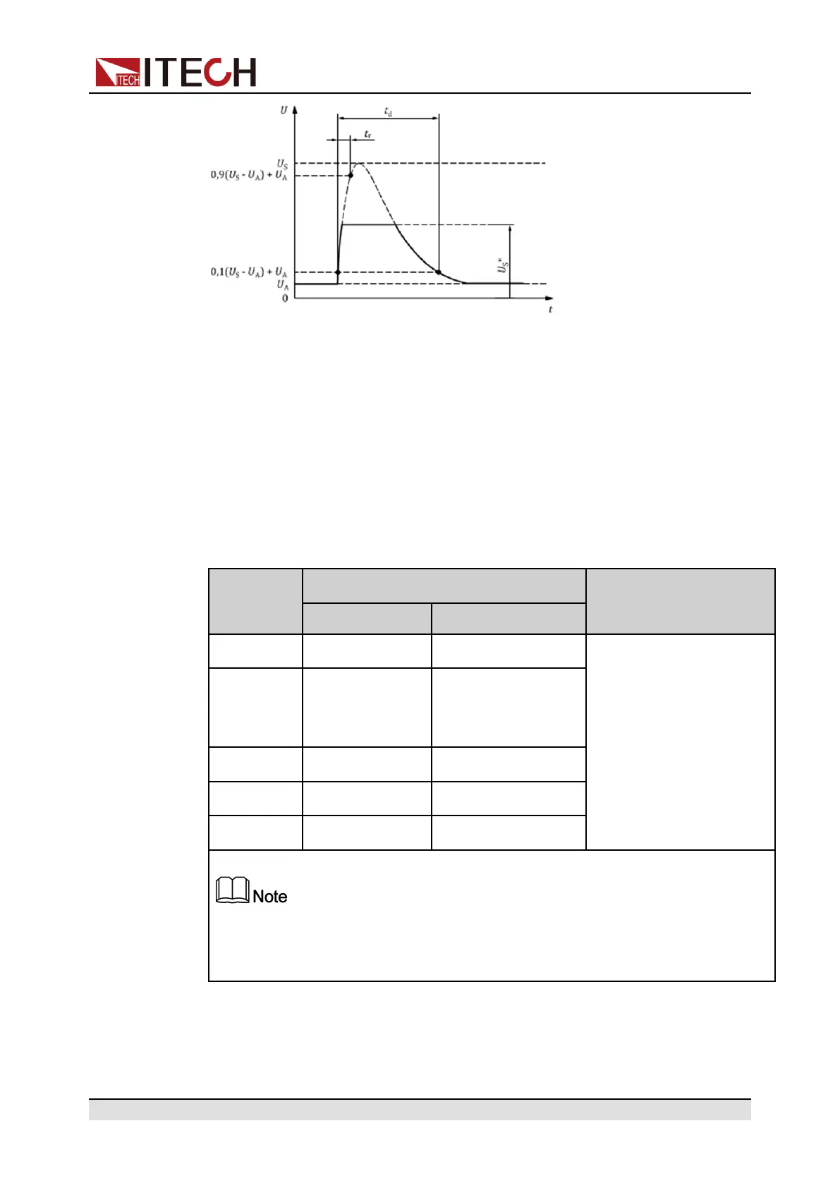
• t: Time
• U: Test voltage
• t
d
: Duration of pulse
• t
r
: Rising Slope
• U
A
: The supply voltage of the generator in operation: U
A
=14V in the 12V sys-
tem, U
A
=28V in the 24V system. (see ISO 16750-1)
• U
S
: Peak voltage
• U
S
*: Supply voltage with load dump suppression (i.e. clamping voltage)
Parameter
Type of system
Minimum test
requirements
12V 24V
U
S
a
(V)
79≤U
S
≤101 151≤U
S
≤202
5 pulses at 1 minute
intervals
U
S
*(V)
It is fixed at 35V
here and cannot
be set.
As specified by cus-
tomer (typical value
58)
Ri
a
(Ω)
0.5≤Ri≤4 1≤Ri≤8
t
d
(ms)
40≤t
d
≤400 100≤t
d
≤350
t
r
(ms)
– –
a
If not otherwise agreed, use the upper voltage level with the upper value for in-
ternal resistance or use the lower voltage level with the lower value for internal
resistance.
The following general considerations of the dynamic behavior of alternators dur-
ing load dump apply:
Copyright © Itech Electronic Co., Ltd.
82
 Loading...
