Quick Start
Copyright ©ITECH Electronics Co., Ltd. 10
3. USB Communication cable interface
4. GPIB Communication cable interface
5. AC power socket(fuse contained)
6. Output Sync signal interface and RS485 Communication cable
interface
7. DVM input terminal, Remote measurement terminal and the output
terminal
8. Analog control interface
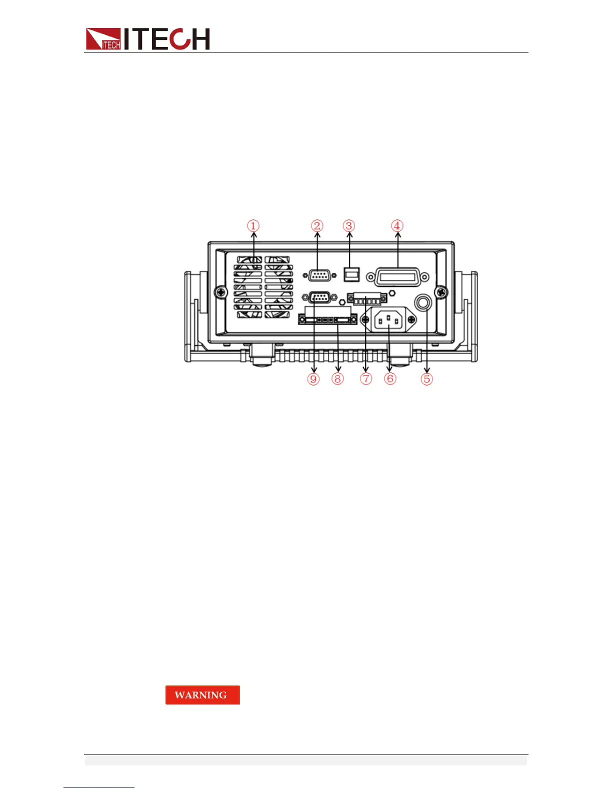
The rear panel of IT6952B/IT6953B is shown in the next figure.
1. Cooling window
2. RS232 Communication cable interface
3. USB Communication cable interface
4. GPIB Communication cable interface
5. Fuse
6. AC power socket
7. Output Sync signal interface and RS485 Communication cable
interface
8. DVM input terminal, Remote measurement terminal and the output
terminal
9. Analog control interface
2.6 Power-on self-test
A successful self-test indicates that the purchased power product meets
delivery standards and is available for normal usage.
Before operation, please confirm that you have fully understood the safety
instructions.
To avoid burning out, be sure to confirm that power voltage matches with
supply voltage.
Be sure to connect the main power socket to the power outlet of protective