EasyManua.ls Logo

ITech IT8516C+ User Manual

ITech IT8516C+
80 pages
To Next Page IconTo Next Page
To Previous Page IconTo Previous Page
Page #41 background image
Functions and Characteristics
Copyright © Itech Electronic Co., Ltd. 32
measured instrument output voltage is 10V, current is 3A, and load current is
switched between 1A and 2A, the transient test parameters and steps are set
as follows:
1. Press [Shift]+[2] (Tran), move key to select ON, press [Enter] to
confirm.
TRAN ON OFF
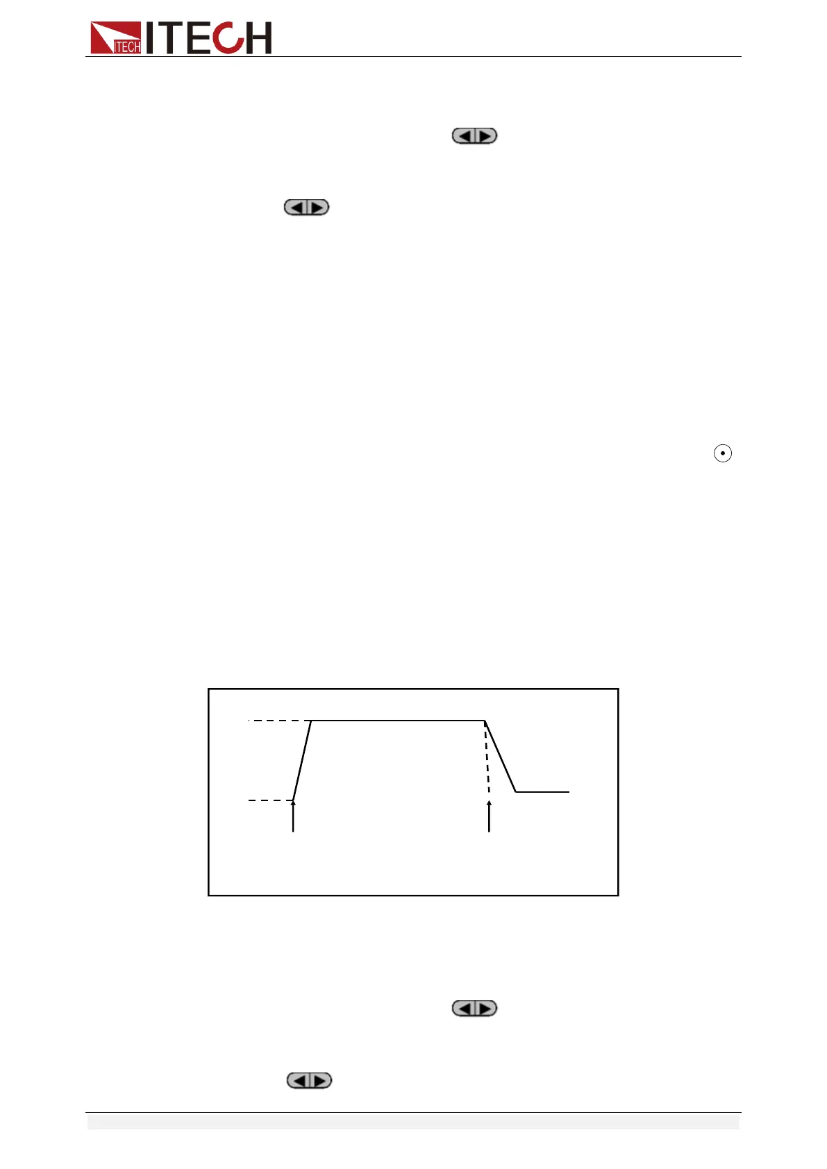
2. Press to select transient operation mode as PULSE (the indicator
lamp Trig will be lighted).
3. Set the rising slope, press [Enter] to confirm.
4. Set the descending slope, press [Enter] to confirm.
5. Set level A, press [Enter] to confirm.
6. Set level B, press [Enter] to confirm.
7. Set the WIDTH, press [Enter] to confirm.
8. Open the transient test function, maintain on the “on selection, press
[Enter] to confirm.
9. Then the VFD will display TRAN and Trig.
10. Press [On/Off] to turn on the input function, and press [Shift]+[ ]
(Trigger) to trigger.
11. Press any key of CC/CV/CR/CW or other composite function keys to exit
the transient test function. If you need to continue transient test parameter
setting and perform transient test, repeat steps 1 to 10.
Toggled Mode
In toggled transient operation, the load starts at the stored parameters for the
mode. When a trigger is received, the load switches to B value. When another
trigger is received, the load switches to the A level. It stays at the A value until
another trigger is received, at which point it switches to the B value. Here’s an
example:
Take CC mode as an example (other modes operate similarly). When the
measured instrument output voltage is 10V, current is 3A, and load current is
switched between 1A and 2A, the transient test parameters and steps are set
as follows:
1. Press [Shift]+[2] (Tran), move key to select ON, press [Enter] to
confirm.
TRAN ON OFF
2. Press to select transient operation mode as TOGGLE (the
indicator lamp Trig will be lighted).
10A
5A
TRG
TRG
Toggled Transient Operation

Table of Contents

Other manuals for ITech IT8516C+

Question and Answer IconNeed help?

Do you have a question about the ITech IT8516C+ and is the answer not in the manual?

ITech IT8516C+ Specifications

General IconGeneral
ModelIT8516C+
CategoryTest Equipment
Output Current0-120A
Voltage Resolution10mV
Current Resolution1mA
Resolution10mV/1mA
InterfaceUSB, RS232, GPIB (optional)
Operating Temperature0°C to 40°C
Storage Temperature-20°C to 70°C
Operating ModeCC, CV, CR, CP

Summary

Chapter 1 Inspection and Installation

Verifying the Shipment

Check package contents and report discrepancies or damage immediately.

Instrument Size Introduction

Details instrument dimensions for proper installation and space selection.

Adjustment of Load Handle

Instructions on how to adjust the load handle for carrying and placement.

Disassembly of Load Handle

Steps to remove the load handle before equipment installation.

Rack Mounting

Guidance on installing IT8500+ series loads on a standard 19-inch rack.

Connect the Power Cord

Precautions and steps for connecting the power cord safely.

Connect the Device Under Test (DUT)

Procedures and safety warnings for connecting the load to the DUT.

Chapter 2 Quick Start

Brief Introduction

Overview of IT8500+ series DC programmable electronic loads.

Product Feature

Lists key features and capabilities of the IT8500+ series loads.

Front Panel Introduction

Describes the layout and components of the front panel.

Front Panel Keys

Details the function of each key on the front panel.

Combination Keys

Explains key combinations for accessing advanced functions.

VFD Annunciators

Describes the meaning of indicators on the Vacuum Fluorescent Display.

Rear Panel Introduction

Identifies and explains connectors and switches on the rear panel.

Power-on Selftest

Outlines the self-test procedure performed upon instrument startup.

Chapter 3 Functions and Characteristics

Local Mode/Remote Mode

Explains how to switch between front panel and PC control.

Operation Mode

Details the four primary operation modes: CC, CV, CR, CW.

Constant Current Mode (CC)

How to set and operate the load in constant current mode.

Constant Voltage Mode (CV)

How to set and operate the load in constant voltage mode.

Constant Resistance Mode (CR)

How to set and operate the load in constant resistance mode.

Constant Power Mode (CW)

How to set and operate the load in constant power mode.

Input On/Off Control

Describes the function of the front panel input On/Off button.

Key Lock Function

How to lock/unlock front panel keys to prevent accidental operation.

Short-circuit Analog Function

How to simulate and measure short-circuit conditions.

System Menu (System)

Navigating and configuring system settings via the system menu.

Config Menu (Config)

Accessing and setting configuration parameters for the instrument.

Trigger Function

Explains the use of triggers for transient and list operations.

LIST Operation

How to create and execute complex test sequences using LIST mode.

Test Function

Overview of various test functions available on the load.

Transient Test Function

Details how to perform transient tests in continuous, pulse, or toggled modes.

OCP Test Function

Procedure for testing Over Current Protection (OCP).

OPP Test Function

Procedure for testing Over Power Protection (OPP).

Battery Discharge Test

Steps for performing battery discharge tests with specified stop conditions.

CR-LED Test Function

How to use CR mode for LED testing, including Vd and R calculation.

Measurement of Voltage Rise Time

Procedure for measuring voltage rise/drop times.

Saving and Recalling Settings

How to save and recall instrument parameter settings.

VON Function

Setting the voltage-on threshold for load activation.

Protection Function

Overview of safety protection features like OVP, OCP, OPP, OTP.

Current Monitoring (I Monitor)

How to monitor input current via an analog output.

Ripple Function

How to measure voltage and current ripple.

Chapter 4 Automatic Test Function

Introduction

General introduction to automatic test functions.

Automatic Test Mode Switching

How to select between IT8500+ and IT8500 compatible modes.

Test Mode for IT8500+

Steps for editing and setting up automatic test sequences for IT8500+.

Test Mode for IT8500

Steps for setting up automatic test sequences compatible with IT8500.

Chapter 5 Specifications

Specifications

Detailed technical specifications for the IT8500+ series.

Supplementary Characteristics

Additional features and operational notes not covered in main specs.

Chapter 6 Communication Interfaces

Communication Modules Introduction

Overview of available communication modules and interfaces.

Communication with PC

How to establish communication between the load and a PC.

Appendix

Specifications of Red and Black Test Lines

Details on optional test cables and their current ratings.

Related product manuals