7
4 - ELECTRICAL CONNECTION AND POWER SUPPLY
AXONIC must be power-supplied by the integrator (CF 51, CF 55 or CF 800) or an exterior power supply. (eg: Itron Pulsbox
or other integrator).
4.1 - Connecting the flow meter to integrator unit
AXONIC is available with 1 or 2 cables, one for output pulse A and one for output pulse B. Beside the main pulse output
A the product could offer (as option) a 2nd pulse output providing pulses and backflow to another independent device
(e.g regulator). This option would be configured at factory.
This pulse output B is following the same hardware specification as output A. Pulse-weight and pulse length of output A and
B are independent.
Before connecting, make sure the pulse weights of flow meter and integrator are equal (typeplate of both devices)!
Connect to integrator according to the following connecting diagram (figures show connecting diagram for CF 51, CF 55,
Pulsbox and CF 800).
Before connecting to other systems make sure that a galvanic insulation is guaranteed. (e.g. by using the Itron Pulsebox)
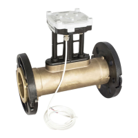
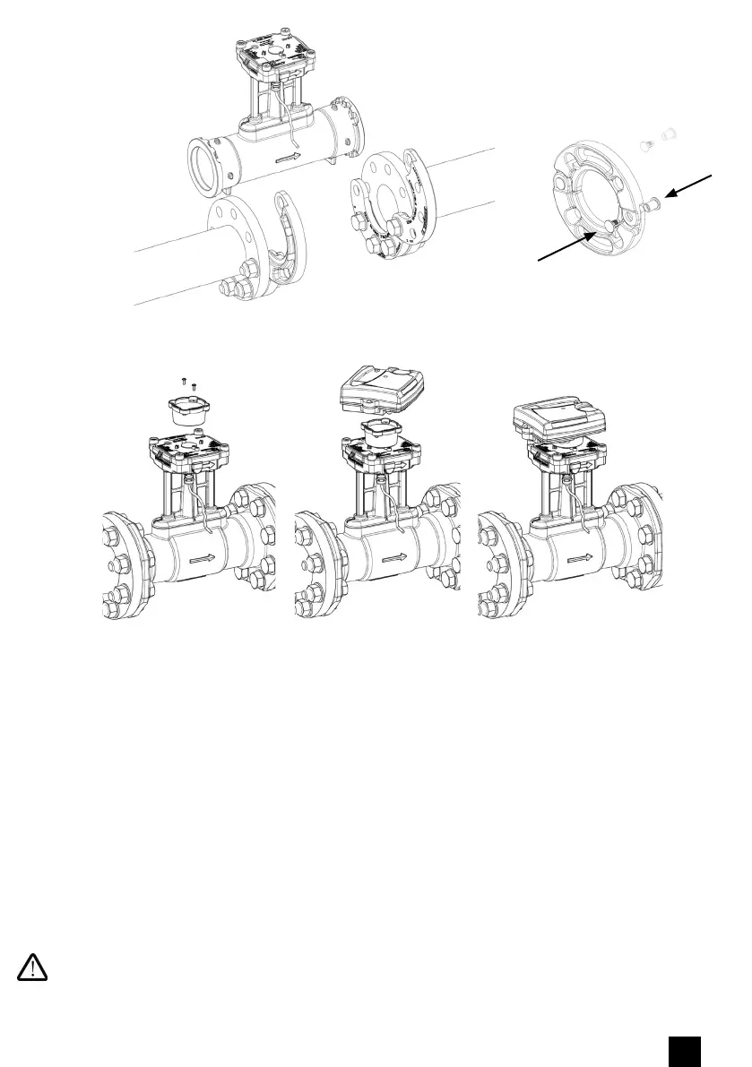
Fig N
o
4: Installation AXONIC with moving flanges
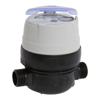
Fig N
o
5: Mounting of an Itron integrator CF51/CF55 onto AXONIC
DN65 - PN16,
DN80 - PN16/25,
DN100 - PN16 :
x4