8
RED
BLACK
BLUE
WHITE
RED
BLACK
BLUE
WHITE
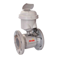
DN65 - qp 25 DN80 - qp 40 DN100 - qp 60 DN150 - qp 150
Pulse Weight Pulse Length (ms)
8 p/L 5 n.a. n.a. n.a.
4 p/L n.a. 5 n.a. n.a.
2 p/L n.a. n.a. 5 5
1 L/p 20 20 10 10
2,5 L/p 50 50 20 50
10 L/p 100** (200, 500) 100** (200) 100 100
25-2500 L/p 100** (200, 500) 100** (200, 500) 100** (200, 500) 100** (200, 500)
**standard: 100ms, values in brackets only if specified in model options table
Always make sure that the housing and gasket line up properly.
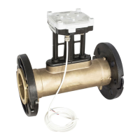
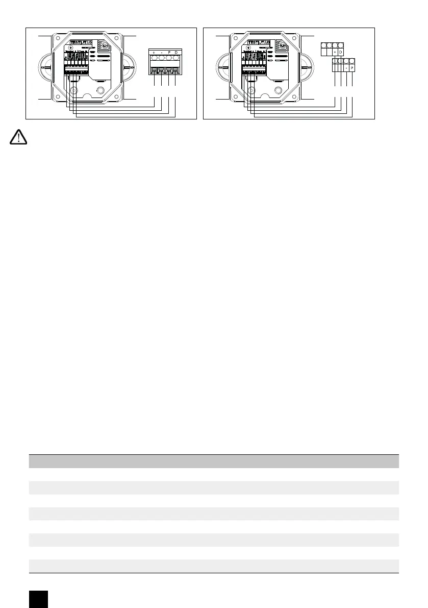
4.2 - Specification of connection to integrator
Cable A: 4 wires connecting cable, used for connection to integrator
Allocation of wire colors:
1 - WHITE: µCom/diagnostic
2 - BLUE: pulse A or diagnostic
3 - BLACK: earth connection (-)
4 - RED: power supply AXONIC (+)
Cable B: 3 wires connecting cable, used for connection to any devices
Allocation of wire colors:
• RED: Pulse B
• BLACK: earth connection (-)
• WHITE: DIR. (Direction of the flow: 1 = normal flow, 0 = backword flow)
4.3 - Characteristic of pulse outputs (A+B):
• conform to class OB, OC and OD of EN1434-2
• Type: Open Drain
• Polarity: non reversible (observe connection diagram)
• Duration of pulse: see table below
• Max voltage: 30V DC
• Max current: 27 mA
• Drop of voltage when switched on: ≤ 0.3V at 0.1 mA /≤ 2V at 27 mA
• Max output frequency: 128 Hz
• Resistance when switched off: ≥ 6MΩ
• Pulse length according table
• Max. cable length: 10 m
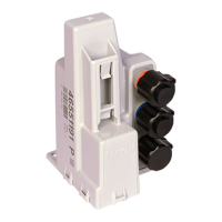
Connection AXONIC/CF51-CF55-Pulse-Box Connection AXONIC/C800