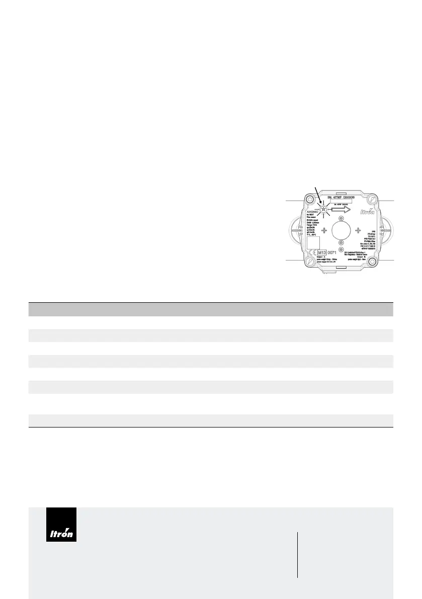
LED
4.4 - Power supply
• Nominal voltage: 3,2 ... 6V DC
• Average current consumption: < 50 µA. (depends on product configuration)
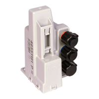
4.5 - Optional connecting AXONIC with Pulse-Box to integrator unit (optional power supply)
The Pulse-Box offers the following functions:
• Power supply of AXONIC independently of the integrator. • Pulse length increase of AXONIC’s pulses.
• Galvanic insulation of AXONIC from the integrator. • 2 wire pulse output
Before connecting, make sure that the pulse of AXONIC and integrator match!
Connection of AXONIC with Pulse-Box to an integrator according to mounting instructions: respect polarities!
Characteristics of pulse exit:
• Version: Open collector
• Polarity: non reversible (respect connecting diagram)
• Duration of impulse: 135 ±35 ms
• Maximum input voltage: 30 V DC
• Max. input current: 27 mA
• Voltage drop when switched on: ≤ 0.3 V at 0.1 mA, ≤ 2.0 V at 27 mA
• Resistance when switched off: ≥ 6 MΩ
• Maximum pulse frequency: 1Hz
• Maximum cable length: 10 m
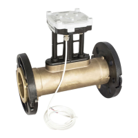
5 - FUNCTION CONTROL OF AXONIC
The AXONIC flow sensor is equipped with a LED in order to perform a simple functional check. The signal sequence
depends on operation conditions and will be repeated any 10 as follow:
Information Number of flashes Signal/Period (Repetition)
Flow detected 1 20ms (LED ON) / 10s
Air in pipe / US Asic alarm 2 20/500ms (LED ON/OFF) / 10s
Low signal amplitude alarm 3 20/500ms (LED ON/OFF) / 10s
Max flow alarm 4 20/500ms (LED ON/OFF) / 10s
Back flow alarm 5 20/500ms (LED ON/OFF) / 10s
Product in test mode Permanent flashing 20/500ms (LED ON/OFF) / permanent
Product configuration un-locked
Flash sequence as above 1…5,
but inverted
500/20ms (LED ON/OFF) / 10s
Product configuration corrupt Permanent ON Permanent (LED ON)
Function control at the calculator:
A functional control and plausibility check shall be done by observing the indications of flow rate and volume index, see
calculators manual and operating instructions.
Putting into operation:
After successful functional test AXONIC is now ready for use and final technical inspection.
• Peak current consumption Imax: < 3 mA
While Itron strives to make the content of its marketing materials as timely and accurate as possible, Itron makes no claims, promises,
or guarantees about the accuracy, completeness, or adequacy of, and expressly disclaims liability for errors and omissions in, such ma-
terials. No warranty of any kind, implied, expressed, or statutory, including but not limited to the warranties of non-infringement of third
party rights, title, merchantability, and fitness for a particular purpose, is given with respect to the content of these marketing materials.
© Copyright 2019 Itron. All rights reserved.
HE-0058.4-ig-ML-10.19 17768-AB
Join us in creating a more resourceful world.
To learn more visit itron.com
ITRON
Allmess GmbH
Am Vossberg 11
23758 Oldenburg in Holstein
Germany
Tel.: +49 4361 625 0
Fax: +49 4361 625 258