MARCH 2004FUEL SUPPLY
6.69
MARINE ENGINES INSTALLATION
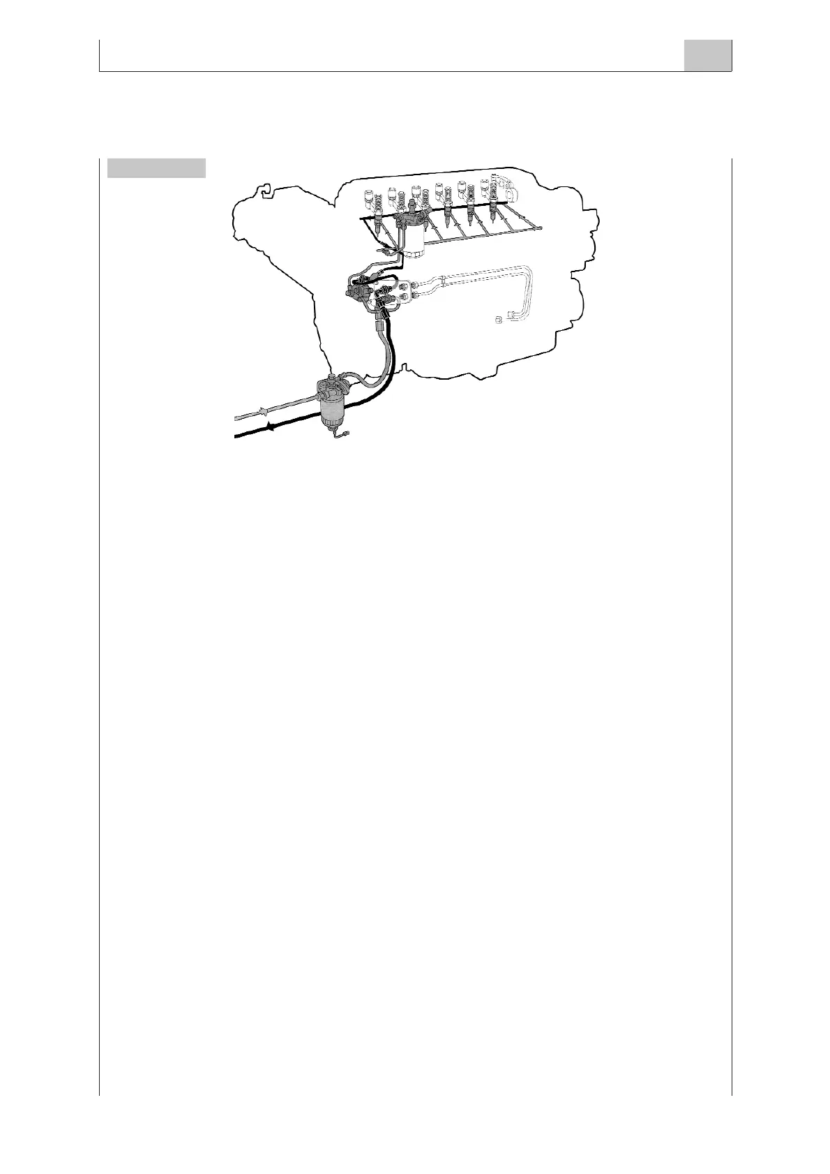
CIRCUIT FOR PUMP INJECTOR SYSTEM (EUI)
Because of the different performances of the injections system, the fuel pressures, temperatures and
capacities have specific values; therefore, you are suggested to see the installation diagrams of each
engine for the prescriptions concerning each different system.
For the correct and regular fuel supply, it is absolutely necessary that all the circuit components, espe-
cially those depending on the fitter-out such reservoir, cocks, pipes, additional filters and other, are
installed accurately and the whole circuit is perfectly waterproof.
The presence of air in the circuit reduces its quickness at start up and generates engine irregularities.
The fuel leaks are a potential fire danger, for this reason it is particularly important to observe fire pre-
vention rules.
6.3 RESERVOIR
The shape and characteristics of the reservoir usually depend on its position on the boat and on the
sailing autonomy, according to the engine adopted. In order to safeguard the boat and the fuel circuit
components, it is necessary to observe the following warnings:
■ The structure must be such to resist the boat bumps at sailing
■ If it is long and low it is advisable to apply breakwater baffles inside.
■ It must be placed far from heat sources, at a limited distance and at the same engine level. If the
reservoir is fitted higher than the engine, foresee the addition of two valves on the suction and
return pipes.The valves shall be kept closed for stops above 24 hours, in order to prevent the pos-
sible fuel flowing back to the engine.
■ Foresee the suitable filler with mesh filter to stop bigger impurities.
■ Foresee a fuel cock applied next to the reservoir on the fuel pipe and in an accessible position.
■ The sucker shall be at no less than 20 mm above the reservoir bottom.
■ The suction and return pipes shall be at about 30 cm to prevent the fuel flowing back affecting
suction.
■ The suction pipe shall be fitted with a pre-filter able to strain deposits bigger than 0.5 mm and such
to prevent the air from getting inside the circuit.
Figure 4
 Loading...
