Basic principles of operation
AirModule 6 720 813 268(2014/10)
36
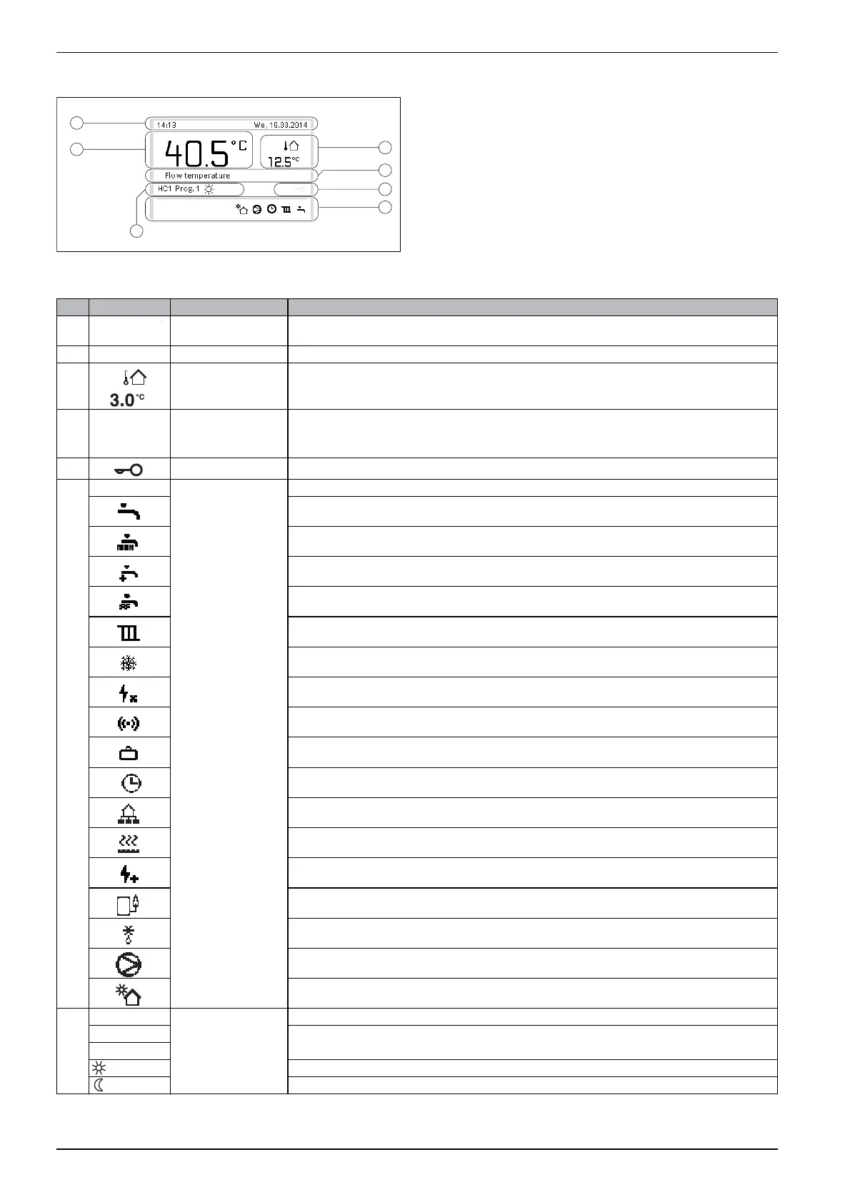
10.2 Display symbols overview
Fig. 35 An example of what the standard display might look like in a
system with several heating/cooling circuits
6 720 811 136-01.1O
6
1
3
7
2
4
5
Pos. Symbol Designation Explanation
1 Temperature Shows current flow temperature (heat pump module temperature)
2 – Information line Displays time of day, day of the week and date.
3 Other temperature
indicator
Displays an additional temperature, e.g. outside temperature, solar panel temperature, or the DHW system
temperature ( user interface operating instructions).
4 – Text information E.g. the designation of the currently displayed temperature ( [1]). No designation is displayed for room
temperature. If an error occurs, corresponding information will be displayed here until the error has been
addressed.
5 Key lock If key lock is enabled, the key symbol appears on the display.
6 Information graphic Displays information symbols, showing the user what functions are currently active in the system.
DHW heating active
Thermal disinfection (DHW) active
Extra DHW function active
Basin/pool is being heated
Heating active
Cooling active
Power outage caused by energy supply company
Closed external input (remote control)
Holiday function active
Time program – heating program 1 or 2 active
Smart Grid (intelligent network) function activated
Screed drying active
Immersion heater active
Extra heat source (booster heater with mixing valve) active
Defrosting active
Heat pump active
Solar pump active
7 Optimised Operating mode Energy efficient operation with a constant set room temperature.
Program 1 The heating is controlled according to the time program active in the current heating circuit. At set times, the
heating will switch between heating mode and setback mode.
Program 2
Heating mode in displayed heating circuit active
Setback mode in displayed heating circuit active
Table 13 Symbols on the standard display