Electric installation
AirModule –6 720 813 268(2014/10)
25
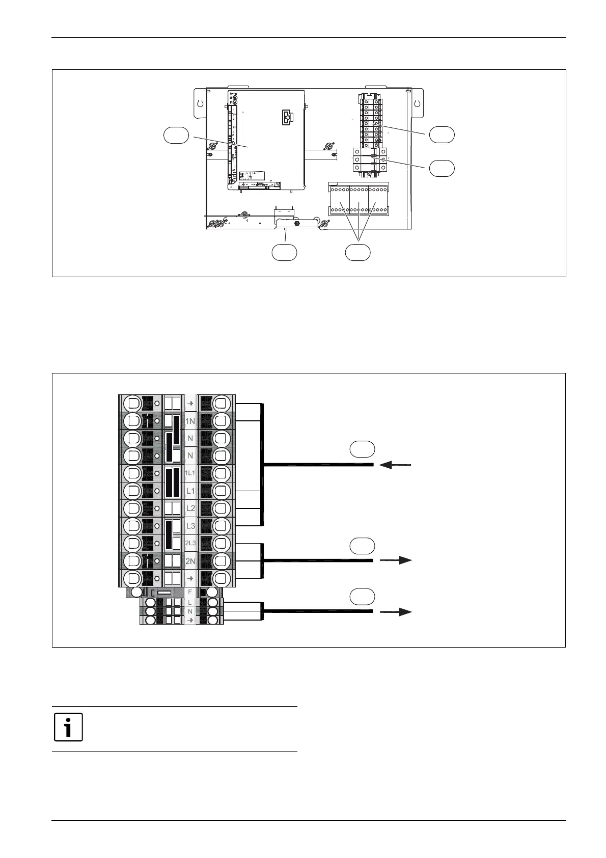
8.7 Electric box layout
Fig. 22 Electric box layout
[1] Terminals
[2] Automatic fuses (only 15 kW model)
[3] Contactors K1, K2, K3
[4] Overheating protection reset
[5] Installer module
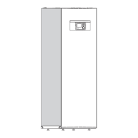
8.7.1 Terminal connections in electric box 9 kW immersion heater 3N~, standard setting
Fig. 23 Terminal connections in electric box
[1] 400 V 3 N~ 16 A, input
[2] 230 V 1 N~, heat pump 5/7/9
[3] 230 V 1 N~, EMS Plus accessories
6 720 809 156-07.2I
1
5
2
4 3
6 720 809 156-16.3I
3
2
1
Immersion heater only on L1 and L2 during heat pump
mode. Otherwise the heat pump must have a separate
power supply from the distribution board.