36
RIGHT MOUNTING
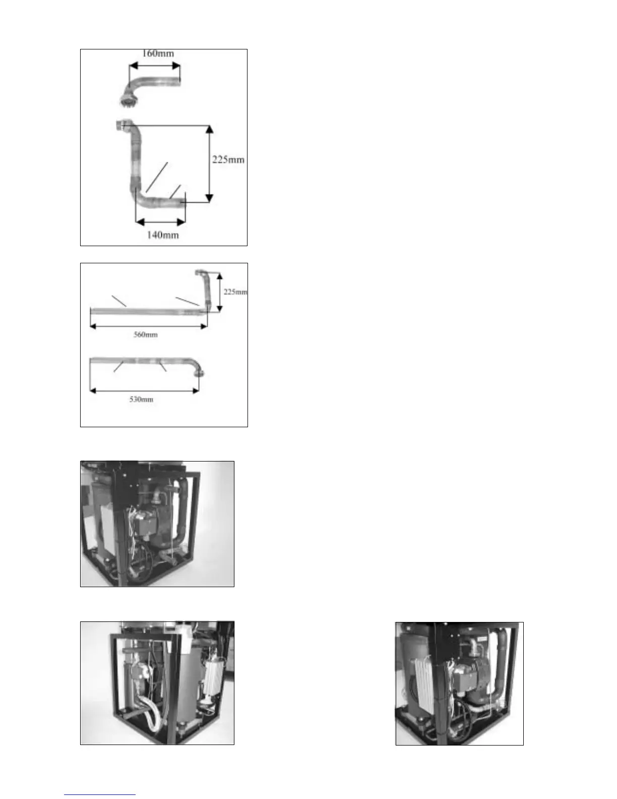
- Heat transfer fluid in is cut as shown in figure A.
- Heat transfer fluid out can be cut as shown in figure B
then a bend and a straight piece of copper pipe can be
soldered in.
The piece of pipe can be taken from the piece that was over
when the pipe was cut.
Do not use compression fittings because of the lack of space in
the heat pump.
LEFT MOUNTING:
- Heat transfer fluid out is cut as shown in figure C then a
bend and a straight piece of pipe are soldered in.
- Heat transfer fluid in is cut as shown in figure D then a
joint and a straight piece of pipe are soldered in.
You can use material that was over when the pipe was cut.
Do not use compression fittings because of the lack of space in
the heat pump.
- When the pipes have been adjusted they are mounted
inplace again.
- The sensor is mounted back on the heat transfer fluid out
with a piece of aluminium tape.
- The armaflex insulation is pushed back onto both pipes. Use
a piece of armaflex tape tocover the pipe properly to avoid
condensation.
The picture on the left shows the heat transfer fluid pipe
mounted on the right before the armaflex insulation is mounted.
Right mounting
Left mounting
View from left and right
D
C
B
A
Soldered
bend
Soldered
bend
Soldered
joint
Straight
section
Straight section
Straight
section
 Loading...