1.18 iZone 325 - Wiring connection to Temperzone units
Unit Make Connection
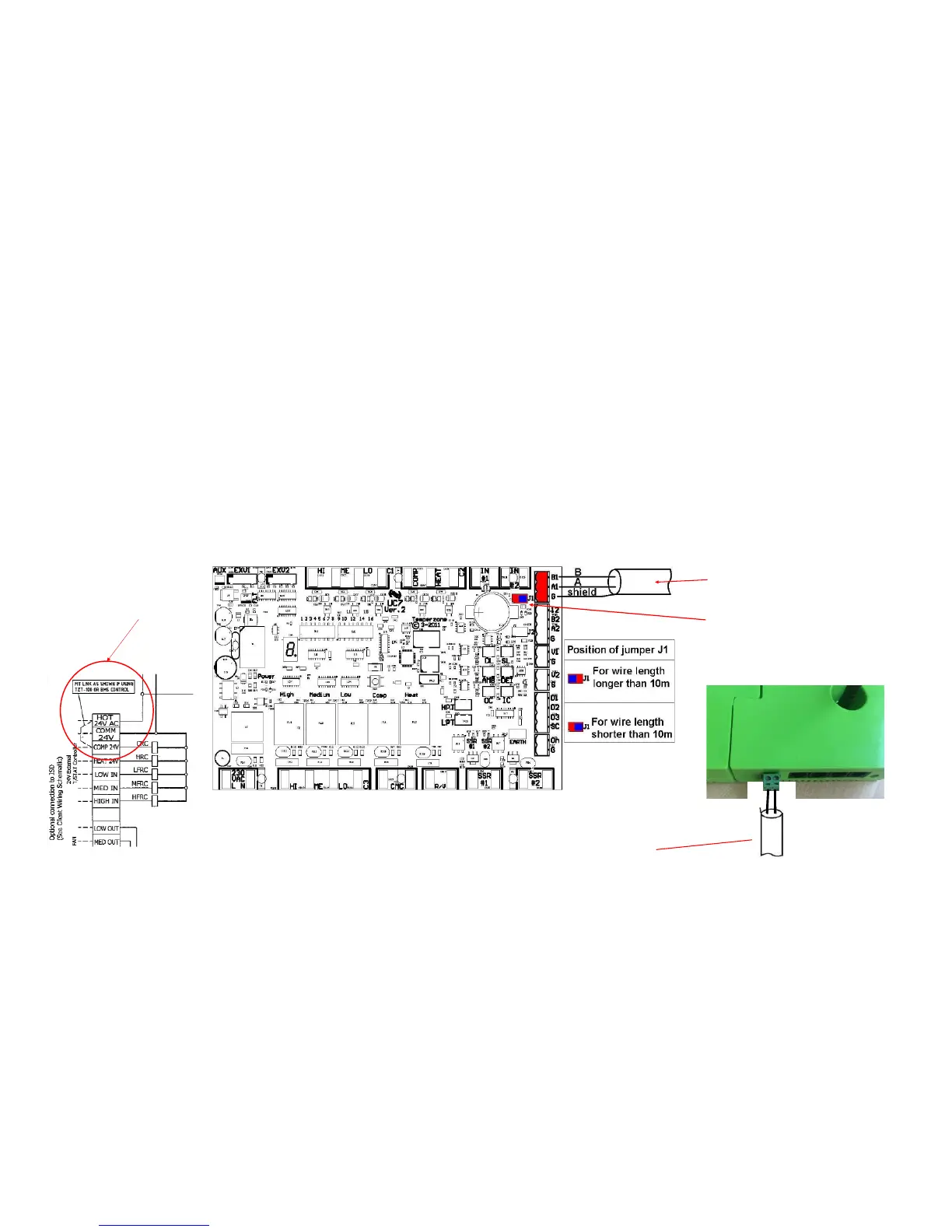
Temperzone 1. Connect a shielded, 2 core, twisted pair control cable from the C225 to the UC7 board in the condensing unit.
(This cable is supplied by the installer). Polarity is critical see Fig A & B for correct connection.
2. Adjust location of jumper J1 to suit the length of control cable installed.
3. Ensure the dip switches in the condensing unit are set correctly for the installed compressor type (digital / fixed
speed) and fan speed control. Refer to the Temperzone service manual.
4. Fit a link as shown in the Temperzone wiring diagram to enable BMS control. This link is between the following
terminal: HOT24V AC and COMP 24V
68*+B%&4,!
$" :(: &'
("('-"*!&&" +
E!E!%&F!('-"
"8$
$" :(:
&'("
('-"*!&&" +
68*=+BD
(
(&"')
=