Do you have a question about the jablotron JA-80-Oasis and is the answer not in the manual?
Door detector with delayed reaction, factory default pre-enrolled.
PIR motion detector with delayed reaction, factory default pre-enrolled.
Keyfob with two buttons, factory default pre-enrolled.
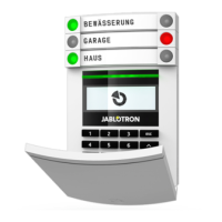
Keypad unit with IN input for magnetic door sensor, factory default pre-enrolled.
Indoor siren with pre-enrolled wireless door-bell button.
Device pre-enrolled to the JA-80L siren.
Attach the Control Panel (CP) to the desired location.
Connect the back-up battery to the CP securely with adhesive tape.
Connect the mains to the CP; the green LED will start flashing.
Connect batteries to the JA-80F keypad; service mode should display.
Install detector, select reaction via DIP switch, connect battery, close cover.
Install detector 2-2.5m high, select reaction via DIP switch, connect battery, close cover.
Plug the JA-80L siren into a mains power socket.
Key in 1 on the keypad while in service mode to enter enrollment mode.
Connect device battery; A indicator confirms enrollment; RC-86 via button press.
Press the # key to exit enrollment mode.
Trigger a device; keypad indicates triggering if functioning and enrolled.
Test motion detectors within 15 mins of closing covers for full sensitivity.
Enter 298 in service mode; trigger device to view signal strength (min 2/4).
Relocate the device if signal strength is less than 2/4.
Ensure CP is in Service mode, enter programming sequences for desired functions.
Press and hold the ? key in Service mode to enter editing mode.
Use keys 1&7, 4&5, 2, and & to navigate, edit, and select text strings.
Exit service mode by pressing the # key.
Demonstrate system operation clearly to the user(s).
Recommend the user change the default master code (1234) to a new one.
The Jablotron JK-84 "Oasis" is a wireless alarm kit designed for security installations, primarily managed by technicians. This system is expandable and features various components for comprehensive protection.
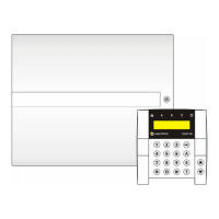
The control panel serves as the central hub of the alarm system. For installation, it should be securely attached to the desired location. Powering the CP involves connecting a backup battery, which should be secured with adhesive tape, and then connecting the mains power. A flashing green LED on the CP indicates proper power connection.
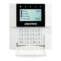
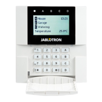
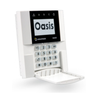
The JA-80F keypad unit requires batteries for operation. Upon connecting the keypad batteries, the keypad should display "service mode." If this mode is not displayed, the keypad batteries should be disconnected, the control panel's power status checked, and then the keypad batteries reconnected. A key feature during keypad battery connection is the ability to select the desired language. By keeping the * key pressed while connecting the batteries, an internal menu opens, allowing language selection (e.g., English = 1). To exit this menu, the # key is pressed. If service mode is exited accidentally, it can be re-entered by keying in * 0 8080. To conserve battery life while in service mode, the keypad's flip cover should be closed.
Before permanently attaching the JA-80F keypad, it's recommended to test its functionality at the intended location. Wiring a magnetic door sensor (included in the kit) to the keypad's IN input is advised. This setup ensures that the keypad "wakes up" when the door is opened, providing system status indications, entrance delay beeps, and enabling the access card reader for card readings.
The JA-81M magnetic detector is installed by selecting its reaction via the internal DIP switch (INS/DEL), connecting its battery, and then closing the cover.
The JA-80P PIR motion detector should be installed at a height of 2 to 2.5 meters above the floor. Its reaction is selected via the relevant internal DIP switch (INS/DEL), its battery connected, and the cover closed.
The JA-80L indoor siren is simply plugged into a mains power socket.
The system can accommodate up to 50 wireless devices. To enroll additional devices, the control panel must be in service mode. If not, * 0 8080 should be entered while the system is unset.
To begin enrollment, 1 is keyed into the keypad. The next vacant address will be displayed, and users can scroll to other addresses using the arrow keys. The device's battery is then connected to enroll it with the CP. Successful enrollment is confirmed by the A indicator lighting, and the next vacant address is displayed.
For the RC-86 key-fob, enrollment is achieved by pressing and holding a pair of its buttons (either + and * or + and 0). Enrollment mode is exited by pressing the # key.
To enroll the CP to UC-82 or AC-82 modules, 299 is entered while the CP is in service mode, with the receiving module in enrollment mode.
To test device functionality, the CP must be in service mode (* 0 8080). The device under test (e.g., a detector) is triggered. The keypad, with its flip cover open, will then indicate the device's triggering if it is functioning correctly and enrolled.
Motion detectors are best tested within 15 minutes of closing their covers. After this initial period, they will only react to frequent movements once every 5 minutes. To restart a device's test mode, its housing must be opened and closed again.
For this check, the CP's antenna must be connected, and the system must be in service mode (* 0 8080).
To initiate the signal check, 298 is entered. The lowest address with an enrolled device will be displayed. The device linked to this address is then triggered. The keypad, with its flip cover open, will show the device's signal strength, ranging from 1/4 to 4/4. A signal strength of at least 2/4 is recommended; otherwise, the device should be relocated.
Similar to functionality testing, motion detectors are best tested within 15 minutes of closing their covers for signal strength. After this, they only react to frequent movements once every 5 minutes. To restart a device's test mode, its housing must be opened and closed.
To test the JA-80F keypad's signal, the connected magnetic door sensor is triggered, or the keypad's tamper sensor is activated.
To test the JA-80L siren's signal, the siren's button is pressed.
The arrow keys are used to select the next enrolled device address.
Signal measurement mode is exited by pressing the # key.
To program the system, the CP must be in service mode (* 0 8080). The appropriate programming sequences are then entered to select the desired functions. A complete list of these functions is available in the CP and communicator manuals.
To edit keypad text strings, the CP must be in service mode (* 0 8080). The ? key is pressed and held to enter editing mode.
Keys 1 and 7 scroll through characters and numbers.
Keys 4 and 5 move the cursor.
Key 2 erases the highlighted character.
Keys * and 0 are used for selecting text strings.
The # key exits editing mode.
Text editing only affects the specific keypad. For more convenient text editing, Olink software on a PC can be used.
To complete the installation, service mode is exited via the # key. The system's operation should be clearly demonstrated to the user(s). It is recommended that the user changes the default master code (1234) to a new master code.
The keypad offers various functions accessible via specific sequences:
5 XXXX (where XXXX is the new code). Factory default is 8080.20x (where x is multiples of 10 seconds). Factory default is 30 seconds.21x (where x is multiples of 5 seconds). Factory default is 20 seconds.22x (where x from 1 to 8 means 1 to 8 minutes, and 9 means 15 minutes). Factory default is 4 minutes.4 hh mm DD MM YY.*5 1234 2789 2789).*6 1234 03 3344 programs user code number 3). To erase a code, enter *6 1234 03 0000.| Zones | Up to 50 wireless zones |
|---|---|
| Users | Up to 50 users |
| Frequency | 868 MHz |
| Type | Wireless |
| Detection method | Various wireless detectors |
| Communication range | Up to 300 m (open area) |
| Communication | GSM, LAN |
| Backup Battery | Not applicable |
| Operating temperature | -10°C to +40°C |