30654-1000
( 1 PAIR )
SNAP-IN PORT X
1/2" (13 mm)
HOSE BARB
STRAIGHT
30653-1000
( 1 PAIR )
SNAP-IN PORT X
3/4" (19 mm)
HOSE BARB
STRAIGHT
30649-1000
( 1 PAIR )
SNAP-IN PORT X
1/2" - 14 MALE PIPE
STRAIGHT
30642-1000
( 1 PAIR )
SNAP-IN PORT X
3/4" (19 mm)
HOSE BARB
90 ELBOW
30651-1000
( 1 PAIR )
SNAP-IN PORT X
1/2" (13 mm)
HOSE BARB
90 ELBOW
30655-1000
( 1 PAIR )
SNAP-IN PORT X
1/2" - 14 MALE PIPE
90 ELBOW
30650-1000
( 1 PAIR )
SNAP-IN PORT X
GARDEN HOSE
STRAIGHT
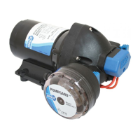
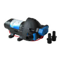
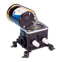
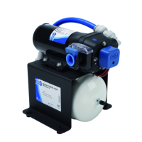
AUTOMATIC WATER SYSTEM PUMP SERVICE PARTS
SERIES SERIES SERIES
KEY# DESCRIPTION 31395 - XXXX 31295 - XXXX 32600-XXXX
1 Pressure Switch 25 PSI (1.7 bar) 18916-1025 18916-1025 18916-1025
40 PSI (2.8 bar) 18916-1040 18916-1040
50 PSI (3.5 bar) 18916-1050
2 Pumphead Assembly 25 PSI (1.7 bar) 18914-1025 18914-0025 18914-1025
40 PSI (2.8 bar) 18914-1040 18914-1040
50 PSI (3.5 bar) 18914-1050
3 Check Valve Assembly 18911-1030 18911-1030 18911-1030
4 Slide Clips (Pair) 30647-1000 30647-1000 30647-1000
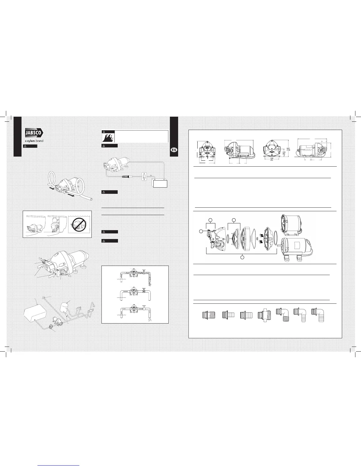
Accessories – Snap-In Port Fittings
MODEL VOLTS AMP DRAW (A) FUSE OPEN FLOW MAX PSI (bar)
@ 10 psi (0.7 bar) SIZE (A) GPM (l/min)
31295-0092 12V dc 3.5 10 1.9 (7) 25 (1.7)
31295-0094 24V dc 1.7 5 1.9 (7) 25 (1.7)
31395-0292 12V dc 4.4 10 2.9 (11) 25 (1.7)
31395-0294 24V dc 2.2 5 2.9 (11) 25 (1.7)
31395-0392 12V dc 4.4 10 2.9 (11) 40 (2.7)
31395-0394 24V dc 2.2 5 2.9 (11) 40 (2.7)
31395-0092 12V dc 4.4 10 2.9 (11) 50 (3.5)
31395-0094 24V dc 2.2 5 2.9 (11) 50 (3.5)
32600-0292 12V dc 9.0 15 3.5 (13.2) 25 (1.7)
32600-0294 24V dc 4.0 10 3.5 (13.2) 25 (1.7)
32600-0092 12V dc 9.0 15 3.5 (13.2) 40 (2.8)
32600-0094 24V dc 4.0 10 3.5 (13.2) 40 (2.8)
3,18
4,24
4,75
3,12 2,25
(121 mm)
(80 mm)
(105 mm)
(80 mm) (63 mm)
9,00
(229 mm)
Dimensional Drawings
INCHES (MILLIMETERS)
Model Reference
Automatic Water
System Pump
Not For Continuous Duty, Intermittent Duty Only
Installation/Mounting
1: Remove shipping plugs from the pump ports.
2: Connect ttings supplied with the pump to the vessels
plumbing. Use ½” (13mm) I.D. exible hose (preferably
braided or reinforced) to reduce vibration through the
plumbing system
(Figure 1). Use
hose clamps on
the slip on barb
hose connectors.
Important:
Install a strainer
in an accessible
location (for
inspection
and cleaning)
between the tank
and the pump inlet to
protect valves from debris.
3: Fasten pump to a at surface. If
mounting vertically; install with pumphead
down (Figure 2) Do not over tighten screws to allow rubber
mounts to absorb vibration.
4: Install inlet (A) and discharge (B) ttings. Firmly push slide
clips (C) forward to lock ttings in place. – Figure 3
.
C.
B.
Figure 3.
Figure 4. Typical Installation
Figure 1.
Figure 2.
Horizontal
Vertical
NOTE: Do Not Submerge
Inlet Port
Fitting
Outlet Port
Fitting
Side Clips
Water
Heater
Water
Tank
Jabsco
City Water
Regulator
Check
Valve
Pumpgard
TM
CAUTION
SI NO ESTÁ FAMILIARIZADO CON LAS
NORMAS ELÉCTRICAS APLICABLES, HAGA QUE UN
ELECTRICISTA CALIFICADO INSTALE LA UNIDAD.
Se provee información del cableado sugerido como referencia. Para
más información, consulte las directrices de la norma E-11 del ABYC,
“Sistemas Eléctricos de CA y CC Instalados en Embarcaciones”.
Tabla de tamaños
de cables
Longitud total del cable – pies (metros)
Voltaje de 0 - 20 pies 20 - 35 pies 35 - 55 pies
la bomba (0 - 6 m) (6 - 9 m) (9 - 12 m)
12 VCC #14 AWG #12 AWG #10 AWG
(2,5 mm
2
) (4 mm
2
) (6 mm
2
)
24 VCC #16 AWG #14 AWG #12 AWG
(1,5 mm
2
) (2,5 mm
2
) (4 mm)
La carcasa del motor puede calentarse durante
el funcionamiento por períodos largos. El contacto prolongado
con la piel puede causar quemaduras.
Instale un ltro Pumpgard™ en una ubicación
accesible (para inspección y limpieza) entre el tanque y la
entrada de la bomba, para proteger a la válvula contra la
acumulación de desechos.
Operación
• Llene el tanque de agua
• Abra todos los grifos
• Encienda la bomba
• Cuando el agua esté libre de aire, cierre todos los grifos
empezando por el más cercano a la bomba (Figura 6)
Importante: No opere la bomba más de 15 minutos seguidos.
!
Figura 5.
Figura 6.
Puesta en marcha inicial
Rojo (+)
Demanda desactivada
Demanda activada
Negro (-)
Fusible
Interruptor
Batería
Peligro de incendio. El cableado debe cumplir las
normas eléctricas aplicables e incluir un fusible
o disyuntor de tamaño apropiado. El cableado
incorrecto puede originar incendios que pueden
causar lesiones o muerte.
ADVERTENCIA
PRECAUCIÓN
PRECAUCIÓN
PRECAUCIÓN
PRECAUCIÓN
9.00
(229)
3.12
(80)
2.25
(63)
4.75
(121)
3.18
(80)
4.24
(105)
Exploded View
32600-XXXX
31X95 - XXXX
1
2
4
3
2.00
(51)
8.90
(226)
3.20
(82)
4.40
(112)
1.60
(40)
 Loading...