EasyManua.ls Logo

Jackle conMIG 400 User Manual

Jackle conMIG 400
72 pages
Go to English
To Next Page IconTo Next Page
Page #1 background imageLoading...
Page #1 background image
conMIG 400 / 445 / 545
mit Steuerbox MC 3, 4, 5 oder 15
und Koffer DVK 3 oder DVK 4
with control box MC 3, 4, 5 or 15
and wire feed case DVK 3 or DVK 4
Deutsch
(Seite 1-24,49-67)
English
(Page 26-67)
Question and Answer IconNeed help?

Do you have a question about the Jackle conMIG 400 and is the answer not in the manual?

Jackle conMIG 400 Specifications

General IconGeneral
BrandJackle
ModelconMIG 400
CategoryWelding System
LanguageEnglish

Summary

Safety Information and Compliance

Safety Check Requirements

Welding units require annual safety checks by qualified personnel per harmonized standards.

Technical Specifications

Power Source Specifications

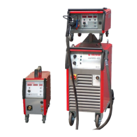
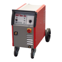
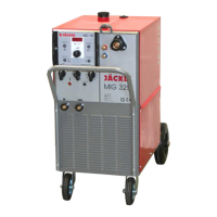
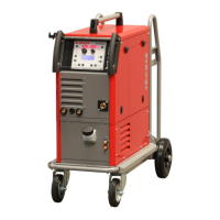
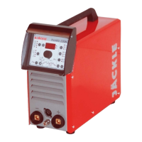
Detailed technical data for conMIG 400, 445, and 545 power sources.

General and Electrical Safety Requirements

General Safety Precautions

Instructions on proper use, maintenance, and modifications for safety.

Electrical Safety and Fire Prevention

Guidelines for welder protection, flammable substance proximity, and cable insulation.

Personal Safety and Gas Cylinder Handling

Personal Protective Equipment (PPE)

Requirements for welder's shield, hearing protection, gloves, and footwear.

Shielding Gas Cylinder Safety

Precautions for handling, storing, and using shielding gas cylinders to prevent explosions.

EMC and Safety Inspection Requirements

EMC and Periodic Safety Inspections

Guidance on electromagnetic interference and mandatory annual safety inspections.

Control Function Overview

Functionality Matrix by Control Unit

Table detailing available functions for MC 3, MC 4, MC 5, and MC 15 control units.

Control Unit MC 3 Operation

MC 3 Function Keys and Knobs

Description of control keys for mode selection, parameter adjustment, and job functions.

Control Unit MC 4 Operation

MC 4 Function Keys and Knobs

Description of control keys for mode selection, parameter adjustment, and job functions.

Control Unit MC 5 Operation

MC 5 Function Keys and Knobs

Description of control keys for mode selection, parameter adjustment, and job functions.

Control Unit MC 15 Operation

MC 15 Parameter Adjustment

How to adjust wire speed, soft start, and burn back time using the knob.

Functional Description of Welding Modes

Automatic vs. Manual Welding Modes

Explanation of automatic preselection and manual parameter adjustment.

Function Fx Parameter Adjustment (MC 3)

Adjusting choke, start speed, burn back, gas times, and spot time.

Functional Description - Advanced Settings

Function Fx Parameter Adjustment (MC 4-5)

Adjusting choke, start speed, and burn back time for MC 4-5.

Material and Gas Settings

Standard Material and Gas Combinations

Table of supported materials, gas mixtures, and corresponding display codes.

Wire Diameter Compatibility

Specification of compatible wire diameters for different materials and gases.

Welding Operation Guide

Mains Connection Procedure

Instructions for connecting the welding unit to the power supply by a qualified electrician.

Torch, Gas, and Workpiece Connections

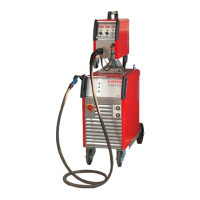
Steps for connecting the welding torch, gas cylinder, and workpiece cable.

Initiating the Welding Process

Steps to set the control box and start the welding operation.

Welding Torch Cooling System

Water Flow Test and Coolant Usage

Performing a water flow test and guidelines for using JÄCKLE coolant JPP.

Maintenance and Safety Checks

Periodic Safety Inspection Schedule

Requirement for annual safety checks by qualified personnel per EN 60974-4.

Advanced Welding Functions

Extended Mode Selection (Cycle/Auto/Manual)

How to select welding modes like 2-cycle, 4-cycle, automatic, or manual.

Troubleshooting Guide

Error Display and Resolution

Common error messages (e.g., T°C, Err H2o, Err CAn) and their solutions.

Spare Parts Identification - Front View (cont.)

Spare Parts Identification - Side View Left (cont.)

Spare Parts Identification - Side View Right (cont.)

Wire Feed Case DVK 3 Parts (cont.)

DVK 3 4-Roller Drive Parts

DVK 4 4-Roller Drive Parts

Circuit Diagrams - conMIG 400

conMIG 400 Circuit Diagram

Electrical schematic for the conMIG 400 model, detailing components and connections.

Circuit Diagrams - conMIG 400 (cont.)

Circuit Diagrams - conMIG 445

conMIG 445 Circuit Diagram

Electrical schematic for the conMIG 445 model, detailing components and connections.

Circuit Diagrams - conMIG 445 (cont.)

Circuit Diagrams - conMIG 545

conMIG 545 Circuit Diagram

Electrical schematic for the conMIG 545 model, detailing components and connections.

Circuit Diagrams - conMIG 545 (cont.)

Related product manuals