EasyManua.ls Logo

Jackle conMIG 445 - User Manual

Default Icon
72 pages
Go to English
Print Icon
To Next Page IconTo Next Page
Loading...
conMIG 400 / 445 / 545
mit Steuerbox MC 3, 4, 5 oder 15
und Koffer DVK 3 oder DVK 4
with control box MC 3, 4, 5 or 15
and wire feed case DVK 3 or DVK 4
Deutsch
(Seite 1-24,49-67)
English
(Page 26-67)
Question and Answer IconNeed help?

Do you have a question about the Jackle conMIG 445 and is the answer not in the manual?

Summary

Technical Specifications and Environmental Requirements

Power Source and Wire Feed Data

Detailed technical data for power sources and wire feed units, including dimensions and noise.

Safety Precautions and Hazards

General Safety Rules and Electrical Hazards

Covers general safety, intended use, electrical precautions, and fire prevention.

Personal Protective Equipment (PPE)

Details essential PPE for welding operations, including eye, hearing, hand, and foot protection.

Shielding Gas Cylinder Safety

Warns about dangers and proper handling of pressurized gas cylinders.

EMC, Inspections, and Disposal

EMC Considerations and User Responsibility

Explains potential interference and user liability for electromagnetic disturbances.

Mandatory Safety Inspections

Details the requirement for annual safety checks by qualified personnel.

Control Panel and Connections

Front Panel Controls Identification

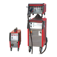
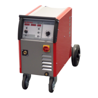
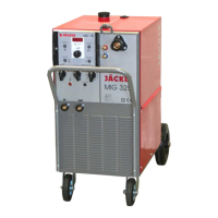
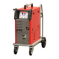
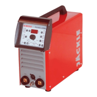
Identifies and labels controls on the front of the welding unit.

Control Unit MC 3 Operation

MC 3 Display and LED Indicators

Explains the function of each display and LED on the MC 3 control unit.

MC 3 Control Key Functions

Details the operation of each button and knob on the MC 3 unit.

Control Unit MC 4 Operation

MC 4 Display and LED Indicators

Explains the function of each display and LED on the MC 4 control unit.

MC 4 Control Key Functions

Details the operation of each button and knob on the MC 4 unit.

Control Unit MC 5 Operation

MC 5 Display and LED Indicators

Explains the function of each display and LED on the MC 5 control unit.

MC 5 Control Key Functions

Details the operation of each button and knob on the MC 5 unit.

Control Unit MC 15 Operation

MC 15 Display and Key Functions

Explains the display and operation of the MC 15 control unit.

Material and Gas Settings Table

Welding Operation Procedures

Unit Installation and Power Connection

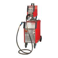
Steps for installing the welding unit and connecting it to the power supply.

MIG;MAG Welding Setup and Start

Guide to connecting torch, gas, workpiece, and initiating the welding process.

Wire Feed Unit (DVK 3;4) Description

Cooling System, Maintenance, and Safety Checks

Troubleshooting Common Issues

Error Messages and Solutions

Lists common malfunctions and their corresponding remedies for quick resolution.

DVK 3 Spare Parts - 4-Roller Drive

DVK 4 Spare Parts - 4-Roller Drive

Electrical Circuit Diagrams

conMIG 400 Circuit Diagram

Provides the circuit diagram for the conMIG 400 power source and wire feed case.

conMIG 400 Circuit Diagram Details

conMIG 445 Circuit Diagram Details

conMIG 445 Circuit Diagram Details (Continued)

conMIG 545 Circuit Diagram Details

conMIG 545 Circuit Diagram Details (Continued)

Power Source and Control Unit Schematics

Schematics for power source, control units, and connections.

Wire Feed Case Connections

Diagram showing connections for the wire feed case.

Jackle conMIG 445 Specifications

General IconGeneral
Input Phase3
Input Frequency50/60 Hz
Output Current445A
Wire Diameter0.8-1.6 mm
Welding Current Range30-445A
Efficiency85%
Duty Cycle60%
Rated Output at 40°C445A

Related product manuals