Do you have a question about the Jackle 150 and is the answer not in the manual?
Explains how plasma cutting works using heat and a concentrated jet.
Highlights benefits like speed, reduced heat, ease of use, and efficiency.
Lists conductive metals suitable for plasma cutting.
Emphasizes adherence to instructions for safe operation and potential hazards.
Covers protection against arc radiation, burning, and flammable substances.
Details necessary protective gear for face, eyes, hearing, hands, and feet.
Addresses ventilation needs and protection from harmful substances during cutting.
Warns about pressurized gas cylinders and safe handling practices.
Discusses electromagnetic compatibility and regulatory compliance.
Outlines mandatory annual safety checks and relevant standards.
Controls the unit's power, with 'O' for off and 'I' for on.
Indicates when the unit is switched on.
Protects the control transformer with a 2 A slow fuse.
Selects cutting current between 75A and 150A.
Illuminates when the torch trigger is pressed.
Signals overheating or low compressed air issues.
Displays the working pressure of compressed air.
Connection point for the workpiece cable.
Proper placement for cooling air and protection from moisture and sparks.
Instructions for connecting the unit to the power supply by a qualified electrician.
Details on connecting the pressure reducer and ensuring adequate air supply.
How to connect the torch hose pack to the central adapter.
Connecting the workpiece cable for good conductivity.
Guidance on selecting the correct plasma nozzle based on cutting current and material.
How to set the cutting current using the weld grade switch.
Procedure for adjusting the working pressure via the pressure reducer.
Steps for initiating the pilot arc and forming the cutting arc.
Techniques for moving the torch for optimal cut quality at a constant speed.
Describes error states indicated by LED flashing patterns.
Explains error conditions for the microprocessor via LED status.
| Brand | Jackle |
|---|---|
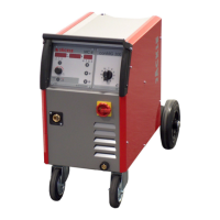
| Model | 150 |
| Category | Welding System |
| Language | English |