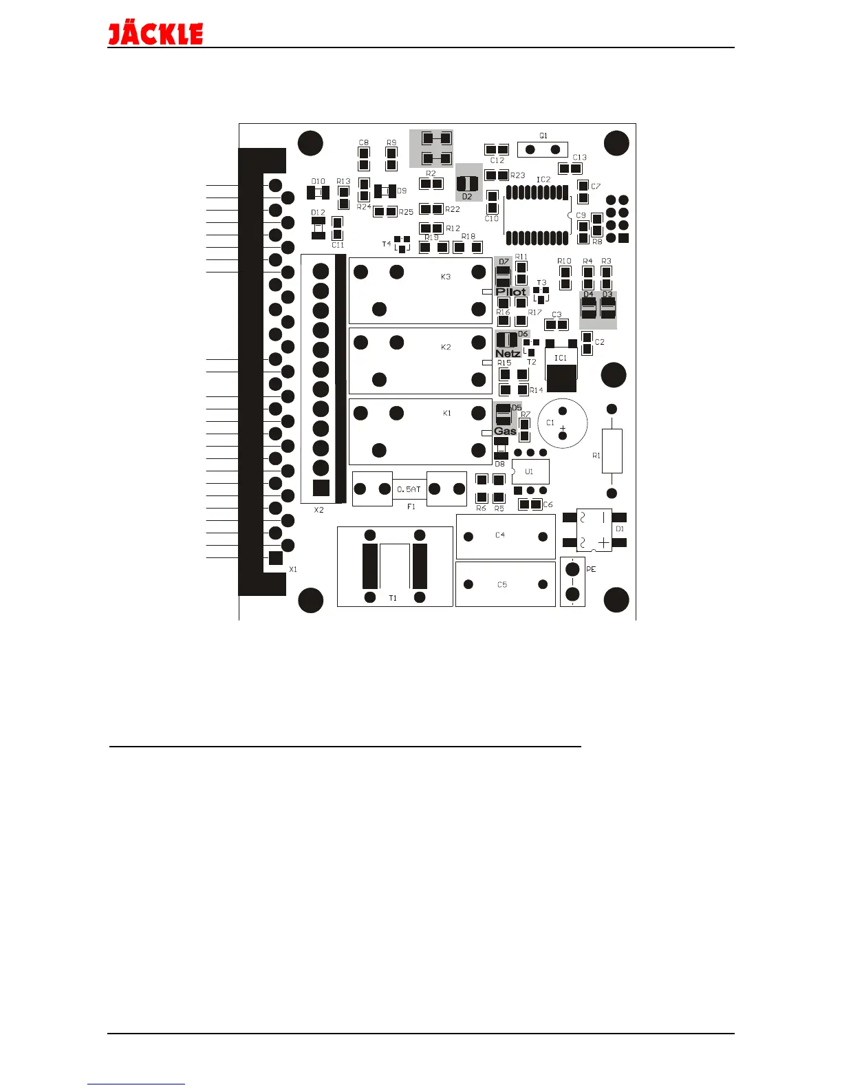
Picture 11.1 View on the PCB PL 3
The components in the grey fields have the following functions:
• The LED D2 ‚5V‘ indicates the correct voltage on the PCB.
• The LED D3 ‚OK‘ shows the normal function of the microprocessor.
• The LED D4 ‚BT‘ shows the function of the torch trigger and the possible errors. They
are described in the next chapter ‘error messages’.
• The LED’s D5 ‚Gas‘‚ D6 ‚Netz‘ and, D7 ‚Pilot‘ are illuminated, when the relay next to
the led is switched on by the microprocessor.