en-51
OPERATION 6
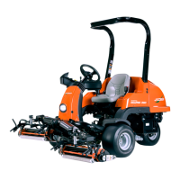
11. Before installing the hydraulic motor ensure that
both spacer rings are fitted. Position the hydraulic
motor over the motor mounting holes, Insert an M10
carriage bolt into each motor mount hole from
beneath the deck ensuring that the carriage bolt
seats correctly. Place a washer (P) and nut (O) onto
each bolt and then tighten to 51 Nm (38 lb-ft).
12. Repeat this instruction for the left and rear (centre)
cutting unit.
Note: Hydraulic hoses removed for clarity.
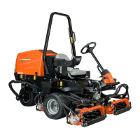
13. For the rear (centre) cutting unit, align the bolt holes
for the centre yoke (F) and yoke brackets (Q)
position number 1 on both sides of the cutting unit.
For the front (left and right) cutting units, align the
shoulder bolt holes for the centre yoke (F) and yoke
brackets (Q) position number 2 on both sides of the
cutting unit.
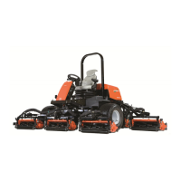
14. Place one M20 washer (R) onto M20 Bolt (S), slide
the M20 bolt (S) through both the centre yoke (F)
and yoke bracket (Q). Install M20 washer (T) and
secure in place with Nyloc nut (U) torque to 27 Nm
(20 ft lb).
15. Repeat process for opposite side.
16. Repeat instructions 13 to 14 for the left and centre
cutting unit.
Note: Decal and hoses are removed for clarity.
17. Start the engine and lift the cutting units into the
transport position, Stop engine and remove key
from ignition switch.
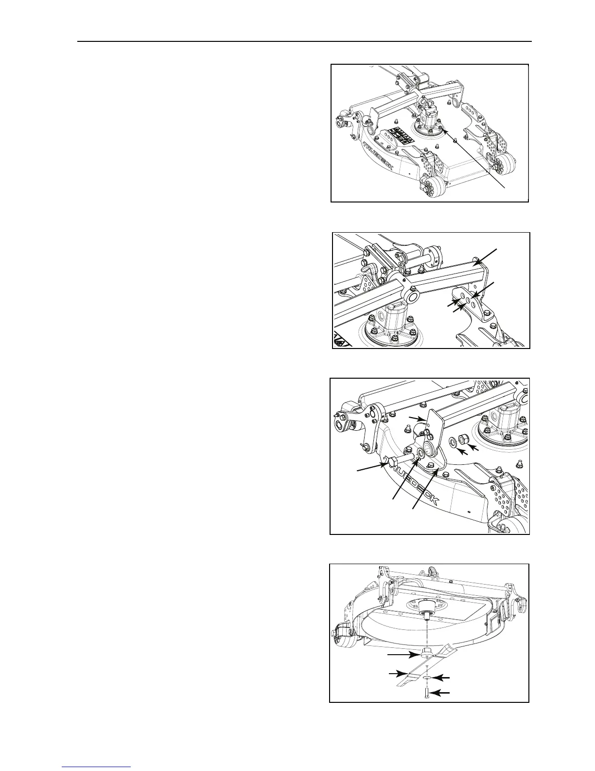
18. Install the blade adapter (V) onto the motor shaft,
ensure that the parallel key is installed.
19. Fit the cutting blade (W) onto the blade adapter (V),
secure in place with blade spacer (X) and blade bolt
(Y), tighten the bolt with your fingers first. Place a
block of wood between the cutting blade (W) and
cutter deck shell, then carefully torque the blade
bolt (Y) to 95 Nm (70 lb ft).
 Loading...