6
Front right
Front left
Subwoofer
R
FM Antenna AM Antenna
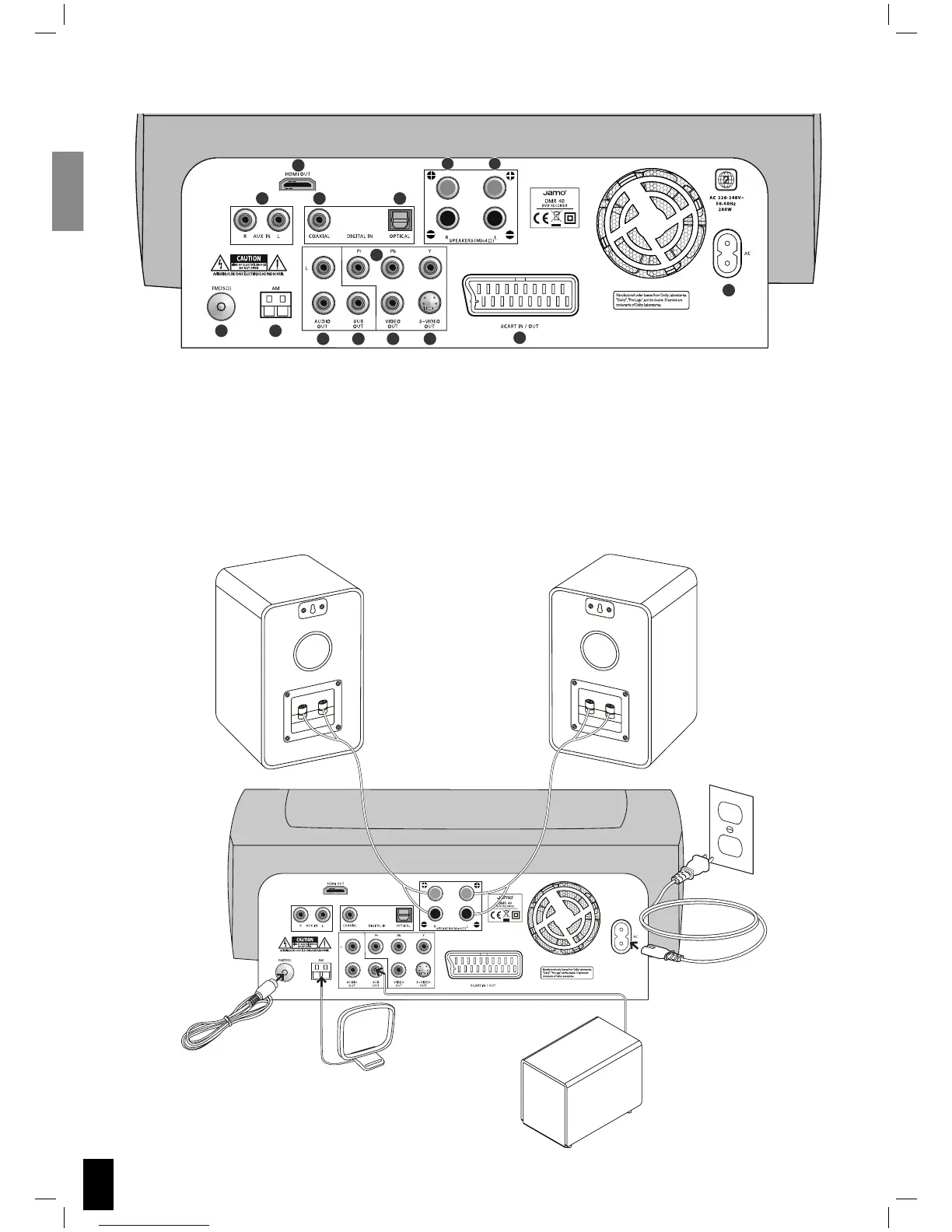
Connecting the system
Refer to the illustration below to connect speakers, subwoofer and antennas. To install the DMR 40 into your current TV sys-
tem, refer to the three configuration examples. Choose from one of them or make your own combination.
Back panel layout
1. FM antenna
2. AM antenna
3. Analogue Audio In - AUX
4. HDMI out
5. Digital In (Co-axial)
6. Digital In (Optical)
7. Analogue Audio Out
8. Subwoofer output
9. Component video out
10. Video Out Composite
11. S-Video Out
12. Front speaker right out
13. Front speaker left out
14. SCART In/Out
(On European model only)
15. Power
1
2
3
4
56
7
9
8 10 11
14
15
R
12
13
 Loading...