Page 11
ENGLISH
Jandy
®
Pro Series VS PlusHP Pumps
|
Installation & Operation Manual
3.2.4.3 Pump Dip Switch Settings
As shown in Figures 5 and 6 the 4 position dip switch
serves two (2) functions: it selects the pump address,
and it determines what type of controller will be used
with the pump.
Table 2. Dip Switch Settings
Switch 1 Switch 2 Controller
OFF OFF Factory Default
OFF OFF AquaLink
®
RS,AquaLinkPDA,
orAquaLinkZ4
ON ON Variable Speed
Controller
Switch 3 Switch 4 Pump Address
OFF OFF PUMP1(FactoryDefault)
ON OFF PUMP 2
OFF ON PUMP 3
ON ON PUMP 4
3.2.5 Auxiliary Load Operation
The VS PlusHP is equipped with a terminal bar that
provides user access to a built-in Auxiliary Load relay
contact. This normally-open, dry contact is activated
under certain operating conditions and is primarily
intended to be used to control external devices that
require system water ow for proper functioning, such
as heaters, booster pumps, salt water chlorinators, etc.
See Figures 5 and 6 for compartment’s location details.
An access cover with Phillips-head screw must be
removed before proceeding.
3.2.5.1 Auxiliary Load Connection
Requirements
WARNING
ELECTRICAL SHOCK HAZARD
Due to the potential risk of fire, electric shock, or injuries
topersons,Zodiac
®
Pumps and any auxiliary loads must
be installed in accordance with the National Electrical
Code
®
(NEC
®
),alllocalelectricalandsafetycodes,and
theoccupationalSafetyandHealthAct(OSHA).Copies
of the NEC may be ordered from the National Protection
Association,470AtlanticAve.,Boston,MA02210,or
from your local government inspection agency.
In Canada, Zodiac Pumps must be installed in
accordancewiththeCanadianElectricalCode(CEC).
• THE Auxiliary Load relay contacts are rated at
230V/11ARMS.Pleaseensuretherequirementsof
theequipmenttobeconnectedtotheAuxiliaryLoad
do not exceed this rating.
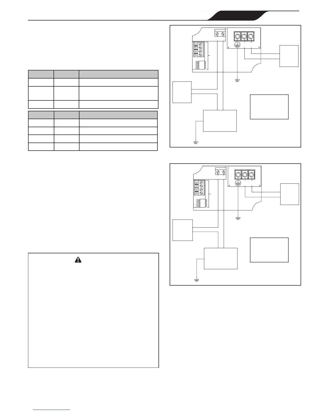
EXAMPLE ONLY
NOT Representative of
all wiring configurations
EXAMPLE ONLY
NOT Representative of
all wiring configurations
Figure 7. 230V Auxiliary Load, Separate Power Sources
Wiring Diagram
F1015 F1014
TP133
TP130
TP127
/100
For
Controller
1 2
230V
Auxiliary
Load
GFCI-
Protected
230V
Power
Source 1
L2 L1
L1
(Black)
L2
(Red or
Black)
Earth
Earth
GFCI-
Protected
230V
Power
Source 2
Line
(Black)
L1
(Black)
L2
(Red or Black)
Note: Recommended Wiring Configuration
Figure 8. 115V Auxiliary Load, Separate Power Sources
Wiring Diagram
F1015 F1014
TP133
TP130
TP127
/100
For
Controller
1 2
115V
Auxiliary
Load
GFCI-
Protected
230V
Power
Source
L2 L1
L1
(Black)
L2
(Red or
Black)
Earth
Earth
GFCI-
Protected
115V
Power
Source
Line
(Black)
Line
(Black)
Neutral
(White)
3.2.6 Auxiliary Load Operation
Characteristics
Auxiliary Load relay contact activation is speed-
dependent, and behaves as follows:
3.2.6.1 Contact Closure
From a stopped condition, there is a three-minute delay
before the Auxiliary Load contact is closed when the
motor speed reaches and maintains a speed of at least
1725 RPM.
From a running condition at below 1725 RPM, there is
a ve-second delay before the Auxiliary Load contact
is closed when the motor speed reaches and maintains a
speed of at least 1725 RPM.