•
SECTION 3
INSTALLATION
BEFORE BEGINNING THE SYSTEM INSTALLATION, REVIEW THE CTI
COMPRESSOR AND COLD HEAD INSTRUCTIONS FOUND IN THE
REFRIGERATOR MANUAL.
3.1 MOUNTING
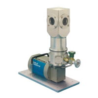
The Janis CCR cold head can be mounted and operated in any convenient orientation. A
mounting base with four 1/4" (M6) clearance holes is provided for mounting to a table or
manipulator. Most systems include four tapped holes on the vacuum jacket bottom
flange for mounting to an optical table with cold finger oriented downwards. The
separate compressor assembly must remain upright to all times.
3.2 POWER REQUIREMENTS
The model 8200 compressor front panel includes switches used to select system voltage
and frequency. Before connecting the compressor to any power source, be sure the
switch configuration matches the available power source. (Refer to page 3-5 in the
compressor manual for additional details).
Most temperature controllers also include selectable voltage settings. Choose the
appropriate voltage by rotating the selection wheel located at the main power connector.
Refer to the controller manual (if applicable) for additional information.
3.3 COMPRESSOR COOLING REQUIREMENTS
Model 8200 compressors are available in either air or water cooled configurations. Air
cooled compressors must be located with free access to the front and rear panels, to avoid
restriction of the air flow. Water cooled compressors require a continuous flow of
cooling water for operation. (Refer to the compressor manual pages 3-3 through 3-5 for
complete details).
•
•
 Loading...