CTI-CRYOGENICS
HELIX TECHNOLOGY CORPORATION
Section 2
Inspection and Installation
2.1 Inspection
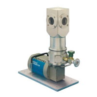
Upon receipt, inspect the Model 22C/350C Cryodyne
Cryocooler for evidence of damage as described below.
Report damage to the shipper at once.
Retain shipping cartons for storage or return shipment.
Inspect the exterior of each cold head for evidence of
damage. Examples of such evidence are a bent cold
station and a dented cylinder.
2.2 Cold Head Installation
Proceed as follows to install each cold head in your
vacuum system. Refer to Appendix K, for the major
interface dimensions of the Model 22/350CP Cold Heads.
1.
Using a clean, lint-free cloth moistened with solvent
such as acetone, carefully clean the groove for the
0-ring in the mounting flange of your vacuum
system.
2.
Using a clean, dry cloth,
sparingly
lubricate the
0-ring with low-vapor-pressure grease; for example,
Apiezon "L" grease. Do not clean the 0-ring
with solvent.
3.
Install the 0-ring in the 0-ring groove.
4.
Carefully install the cold head on the mounting
flange of your vacuum chamber.
Each cold head and related components must have
adequate vacuum integrity for proper operation in your
vacuum system. Inadequate vacuum will result in an
unwanted gas conduction heat load from the room
temperature vacuum housing to the cold surfaces of the
cold head cold stations. A small vacuum leak will cause
high-than-normal cold station operating temperatures,
combined with a gradual temperature increase; a large
vacuum leak may prevent satisfactory cooldown. The
rough-pumping system should be isolated from your
vacuum system, once cooldown has started, by closing
the roughing valve.
It is recommended that a suitable pressure relief valve
be installed in your vacuum system to prevent any
possible positive pressure rise during warm-up.
P/N 8040272
2-1
 Loading...