CTI-CRYOGENICS
HELIX TECHNOLOGY CORPORATION
Section 4
Functional Description
This Section presents additional detail description of
each cold head and the compressor. Knowledge of the
content of this Section is not required in order to operate
your cryocooler. The information is included in this
Manual for the benefit of those readers who desire a
more comprehensive understanding of the functional
operation of the Cryodyne cryocooler.
4.1 Model 22/350CP Cold Heads
(see Figures 1.1 and 1.2)
The function of each cold head is to produce
continuous closed-cycle refrigeration at temperatures
that, depending upon the heat load imposed, are in the
range of 40K to 100K for the first-stage cold station and
in the range of 10K to 20K for the second-stage cold
station.
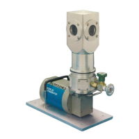
The cold head has three major components: the drive
unit; the cylinder; and the displacer-regenerator
assembly, which is located inside the cylinder.
The drive unit consists of the following subassemblies:
the drive motor; the crankcase; and the drive mechanism,
which is located inside the crankcase. The drive unit
actuates the displacer-regenerator assembly and controls
the flow of helium into and out of the cold head.
The motor employed is a direct-drive, constant-speed
motor that operates at the following speeds for 50 or 60
Hz power applications.
COLD HEAD
FREQUENCY
(HZ)
MOTOR RPM
Model 22
50
167
60
200
Model 350CP
50
60
60
72
Each motor housing has two connectors: one is the
electrical power connector, through which power is
supplied; the other is the helium-gas return connector.
Functionally, the incoming high-pressure helium gas
from the compressor enters the cold head through the
helium-gas supply connector. The gas then passes into
the displacer-regenerator assembly, flows out through
the displacer-regenerator assembly, into the crankcase,
through the motor housing, and finally through the
helium-gas return connector to the compressor. The
helium gas expansion in the displacer-regenerator
assembly provides cooling at the first and second-stage
cold stations, each at different temperatures.
Refer to Appendix C for a detailed explanation on the
principles of operation.
P/N 8040272
4-1
 Loading...