Do you have a question about the Janome JR3303N-AJ and is the answer not in the manual?
Describes how to read the sample identification plate on the robot.
Shows the locations of the identification plates on different robot series.
Explains the two types of I/O polarity (NPN and PNP) and power supply indications.
Provides detailed external dimension diagrams for various robot models.
Details the mounting points and fixture locations on the robot base.
Specifies installation height recommendations for the teaching pendant.
Shows installation height recommendations and dimensions for the switchbox.
Explains I/O polarity and power supply indications for the I/O-SYS.
Lists the pin numbers and their corresponding insulator colors for the I/O-SYS.
Provides a table detailing cable wiring with pin numbers and insulator colors.
Specifies the output capacity (voltage and amperage) for internal and external power supplies.
Shows circuit diagrams for NPN input signals with external and internal power supplies.
Shows circuit diagrams for NPN output signals with external and internal power supplies.
Detailed circuit diagrams for NPN input and output signals.
Shows circuit diagrams for PNP input signals with external and internal power supplies.
Shows circuit diagrams for PNP output signals with external and internal power supplies.
Detailed circuit diagrams for PNP input and output signals.
Explains I/O polarity and power supply indications for the I/O-1 connector.
Lists pin numbers and their corresponding names for the I/O-1.
Details function assignments for input, output, and other categories for I/O-1.
Provides a table for cable connection details, including pin numbers and colors.
Specifies the power supply capacities for I/O-1 output and input pins.
Shows circuit diagrams for NPN input signals with external and internal power supplies for I/O-1.
Shows circuit diagrams for NPN output signals with external and internal power supplies for I/O-1.
Detailed circuit diagrams for NPN input/output signals for I/O-1.
Shows circuit diagrams for PNP input signals with external and internal power supplies for I/O-1.
Shows circuit diagrams for PNP output signals with external and internal power supplies for I/O-1.
Detailed circuit diagrams for PNP input/output signals for I/O-1.
Shows the I/O-S connector locations on different robot series.
Lists the pin numbers for the I/O-S connector.
Explains connecting safety devices and short-circuiting the connector when not used.
Describes how to set up Fieldbus module types using the teaching pendant or PC.
Details DeviceNet connector diagram, network/module status LEDs, and pin assignments.
Details Profibus connector diagram, operation/status LEDs, pin assignments, and settings.
Details CC-Link connector diagram, run/error LEDs, pin assignments, and settings.
Shows the I/O-MT connector locations on different robot series.
Lists pin numbers for the I/O-MT connector.
Details function assignments for MT1 and MT2 inputs, outputs, and pulse outputs.
Provides cable wiring details for the I/O-MT connector.
Specifies output capacities for I/O-MT pins and input signal requirements.
Shows circuit diagram for I/O-MT input signals.
Shows circuit diagram for I/O-MT output signals.
Detailed circuit diagrams for I/O-MT input and output signals.
Explains how to record and retrieve teaching data using USB memory.
Describes how to update system software and PS data via USB memory.
Details settings for the memory port and auto-update functions.
Describes the standard Ethernet connector and its functions.
Lists the pin assignments for the LAN port.
Shows the locations of COM1, COM2, and COM3 connectors on robot series.
Lists the pin numbers for the COM ports.
Details pin connection mappings for COM ports to PC (D-Sub 9/25 pin).
Shows the location of the teaching pendant connector on robot series.
Lists pin numbers for the teaching pendant connector.
Details RS422 interface pin connections for the teaching pendant.
Circuit diagram for the teaching pendant connector, including safety circuit.
Shows the location of the switchbox connector.
Lists pin numbers for the switchbox connector.
Circuit diagram for the switchbox connector, including emergency stop and motor driver inputs.
Lists commands for ON/OFF Output Control and Condition.
Lists commands related to execute conditions.
Lists commands for PLC programs (Contact Point, Coil, Connection, Others).
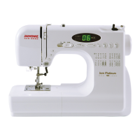
| Brand | Janome |
|---|---|
| Model | JR3303N-AJ |
| Category | Sewing Machine |
| Language | English |


 Loading...