Page: 15
FM-200® FILL MANUAL
Revision B
Document # DOC180
Issued: August 16, 2010
Revised: April 2, 2012
Section 4 Fill Procedure
4 FILL PROCEDURE
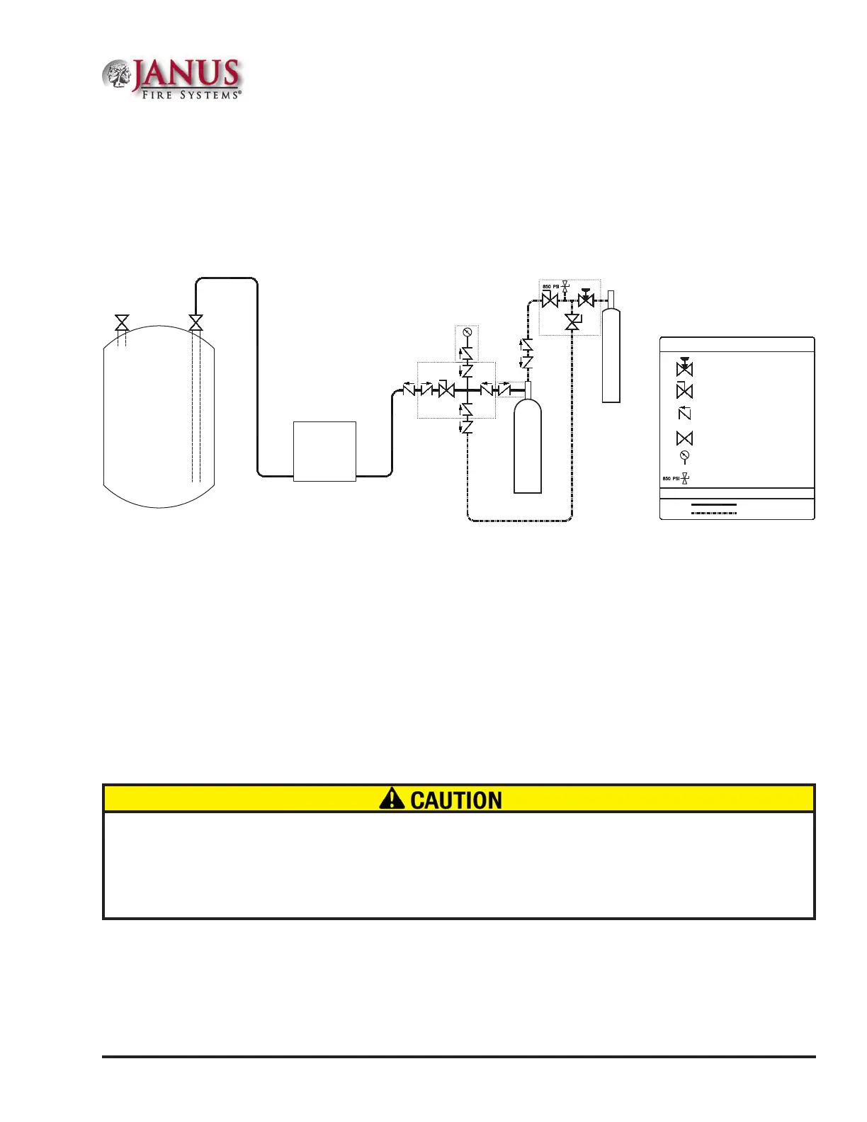
is section contains a step-by-step procedure for weighing, lling, pressurizing, and closing the cylinder
assembly. Refer to Figure 4 for a P&ID diagram that illustrates how each cylinder ll component connects
to the agent ll station, nitrogen supply, and cylinder assembly. Each component should be only installed
when indicated in the sections that follow.
SYMBOL LEGEND
PRESSURE REGULATING VAVLE
PIPING / HOSE LEGEND
NITROGEN LINE
AGENT FILL LINE
AGENT SUPPLY LIQUID LINE
AGENT SUPPLY VAPOR LINE
PUMP
IN
OUT
SYSTEMS
VALVE CLOSING LINE
CYLINDER PRESSURIZATION LINE
NITROGEN
CYL. FILL ASSY.
SUPPLY
TANK
CYLINDER
SUPPLY
FM-200
GAUGE ASSY.
FILL
ADAPTOR
REGULATOR/HOSE ASSY.
BALL VALVE
CHECK VALVE
SUPPLY TANK VALVE
PRESSURE GAUGE
RELIEF VALVE
4.1 Log and Weigh Empty Cylinder
• Record the serial number of the cylinder assembly in the appropriate section of the ll log. Record the
agent lot number from the supply of FM-200®, the ll station number from the agent ll station, and
the date of the ll in the appropriate sections of the ll log and cylinder label.
• Place the empty cylinder assembly on a calibrated scale. Record the weight displayed on the scale in the
appropriate section of the cylinder label and ll log as the empty weight. NOTE: e anti-recoil safety
device shall remain installed in the empty cylinder assembly during weighing. e ll adapter, cylinder
ll assembly, or valve closing adapter shall not be installed during weighing; do not include the weight
of any ll component in determining the empty cylinder weight.
Any trim components installed in the empty cylinder assembly prior to the initial weighing (including anti-recoil
safety device, pressure gauge, and/or low-pressure supervisory switch) shall be installed and included in all
proceedingweightmeasurementsduringthecourseofthellprocedure.Anytrimcomponentsnotinstalledon
the empty cylinder assembly during the initial weighing shall not be installed or included in any proceeding weight
measurements. Failure to maintain a consistent hardware base for weighing purposes may cause inaccuracy
when using these weights to determine the amount of agent contained in the cylinder assembly.
4.2 Agent Fill Procedure
NOTE: Prior to initiating the agent ll procedure, determine the ambient temperature of the lling location.
Compare this temperature to the values listed in Table B.1 located in Appendix B to determine the nal
cylinder pressure required to provide a cylinder pressure of 360 psig at 70°F.
Figure 4 Cylinder Fill P&ID Diagram
 Loading...