Page: 25
FM-200® FILL MANUAL
Revision B
Document # DOC180
Issued: August 16, 2010
Revised: April 2, 2012
Section 5 System Recharge and Reset
• RemovethecollarO-ringanddiscard.
• TopreventdamagetothenewcollarO-ringduringinstallationcoverthethreadsofthevalvebodywith
masking tape.
• LightlylubricatethenewcollarO-ringwithMolykote55byDowCorning(P/N19056)orequivalent
and install on the valve body.
• Cleanthethreadsonthediptubeandthreadintothevalvebodyassembly.Tightensecurely.
• Removemaskingtapeandcleanthecollarthreadsonthevalvebody.Cleantheseatingsurfaceofthe
cylinder collar. Install valve assembly into cylinder, tighten securely.
• Reinstallthelow-pressuresupervisoryswitchandpressuregaugeassembliesonMvandLvSeriesvalve
assemblies.
5.2.3 Recharge Procedure
• FollowtheproceduresoutlinedinSection4ofthismanualtollthecylindertothecorrectamountby
weight and pressurize the cylinder assembly to 360 psig at 70°F. See the cylinder label for ll weight
and ll to a minimum of the stamped ll weight and no more than ¼ pound (4 oz) (113 g) above the
stamped ll weight. e pressure gauge on the cylinder shall not be used to determine when the proper
charge pressure has been reached. A pressure regulator must be used when the pressure source is a tank
of high pressure gas.
• ReplacethechargedcylinderinthebracketandfollowproceduresoutlinedinSection4andSection5
of the Installation Manual, DOC102, to reinstall the system.
• Informappropriatepersonnelthatthesystemisbackinservice.
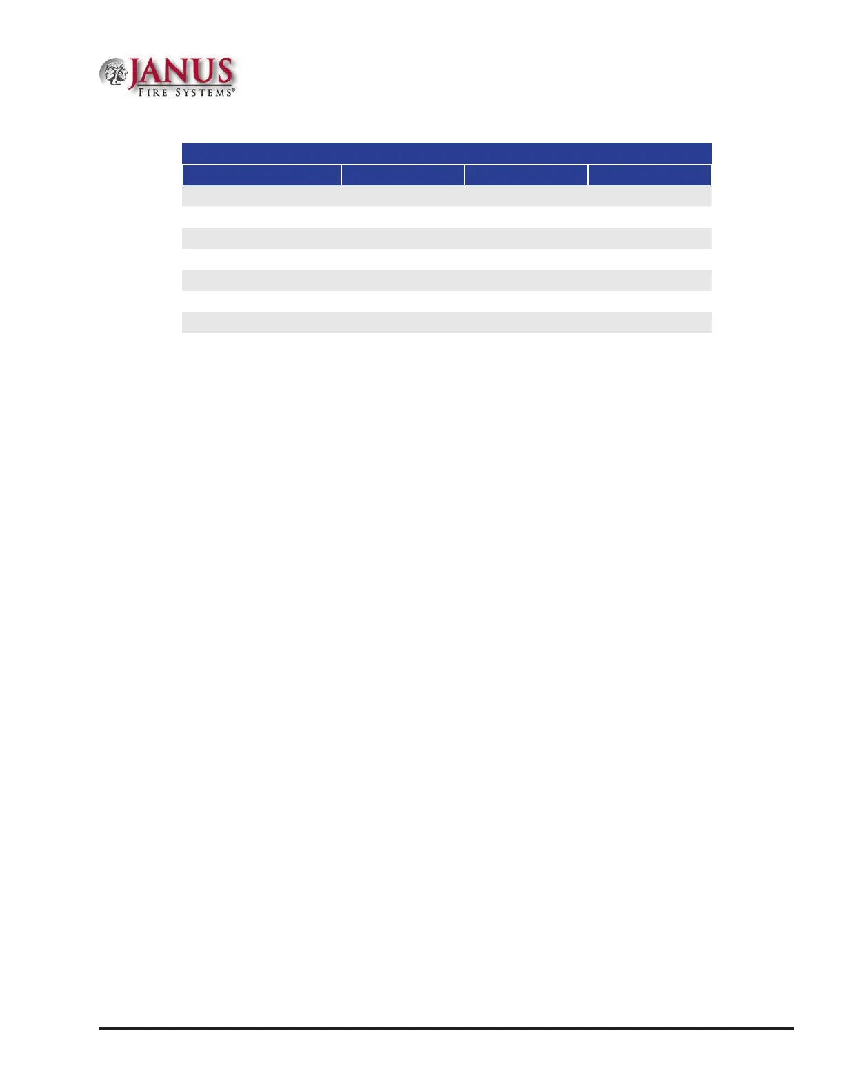
Table 5.2.2 Valve Replacement Components
Part Description Sv P/N Mv P/N Lv P/N
Collar O-ring 17551 18400 18400
Upper Piston O-ring 17552 18475 18398
Lower Piston O-ring 17553 18476 18399
Valve Cap O-ring 17551 18399 18397
Valve Core 16999 16999 16999
Piston Assembly 17335 18471 18393
Valve Rebuild Kit
1
17030 19019 19020
1
Valve Rebuild Kit includes the appropriate collar O-ring, valve cap O-ring, piston assembly (with upper
and lower piston o-ring), and valve core for the cylinder valve indicated by the kit part number.
 Loading...