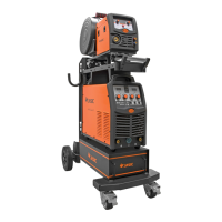
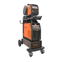
3.2 Installation Setup For MIG with Gas
[1] Insert the earth cable plug into the negative socket on the front of the machine and tighten it.
[2] Connect the weld power cable to the positive socket.
IMPORTANT: When connecting the torch be sure to tighten the connection. A loose connection
can result in the connector arcing and damaging the machine and gun connector. This damage is
not covered under warranty.
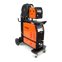
[3] Connect Gas Line to Gas Regulator and connect the gas regulator to the Gas Cylinder.
[4] Check the Weld Power Cable is connected to the positive terminal.
[5] Place the Wire Spool onto the Spool Holder-Note: the spool retaining nut is top thread. Snip the
wire from the spool being sure to hold the wire to prevent rapid uncoiling. Feed the wire into the
wire feeder inlet guide tube through to the drive roller.
[6] Carefully feed the wire over the drive roller into the outlet guide tube, feed through about 150mm
Into the torch receptacle. Check that the drive roller being used complies with the wire diameter,
Replace the roller if necessary.
[7] Align the wire into the groove of the drive roller and close down the top roller making sure the
wire is in the groove of the bottom drive roller, lock the pressure arm into place.
[8] Apply a medium amount of pressure to the drive roller.
[9] Remove the gas nozzle and contact tip from the torch neck.
[10] Press and hold the MIG Torch switch to feed the wire through to the torch neck.
[11] Fit the correct sized contact tip and feed the wire through it, screw the contact tip into the tip holder
of the torch head and nip it up tightly.
[12] Fit the gas nozzle to the torch head.
[13] Carefully open the gas cylinder valve and set the flow rate to between 5-10L/min.
[14] Select the correct sized wire diameter.
[15] Select welding parameter required on ‘synergic’ knob,
based on the mater ial thickness of the work piece.
[3] Connect the
gas line to the
regulator and
connect to the as
cylinder
[2] Connect weld power lead to“+”
[1]Connect earth lead to
“
-
”

 Loading...