Do you have a question about the JBL 6230 and is the answer not in the manual?
Details technical specs: output power, impedance, frequency response, noise levels.
Instructions for safely unpacking and checking amplifier for transit damage.
Discusses optimal operating conditions and amplifier cooling requirements.
Details AC power requirements, voltage verification, and grounding safety.
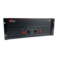
Explains rear panel switch for Stereo, Dual Mono, or Bridged Mono modes.
Covers input/output connectors: jacks, XLR, barrier strips, and binding posts.
Explains input impedance characteristics and termination for signal integrity.
Discusses user responsibility to avoid overpowering loudspeakers and select appropriate loads.
Discusses speaker cable types, DC resistance, and durability.
Details importance of proper grounding for safety, noise reduction, and shielding.
Describes installation and use of optional security covers for gain controls.
Guidelines for amplifier installation and initial setup before powering on.
Procedure for powering on the amplifier and verifying system operation.
Explains CLIP LED function and interpretation.
Clarifies amplifier sensitivity ratings and relation to input signal levels.
Details function and design of the input differential amplifier stage.
Describes mode switch effects on signal routing for Stereo, Dual Mono, Bridged Mono.
Explains discrete transistor circuitry and symmetrical topology of the power amplifier stage.
Details circuitry for output relay driver and DC output detection.
Explains clip detection circuit operation and associated LED.
Describes conventional power supply design and voltage regulation.
Notes on amplifier construction, reliability, and no required preventive maintenance.
Details factory warranty, return procedures, and repair recommendations.