9
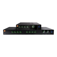
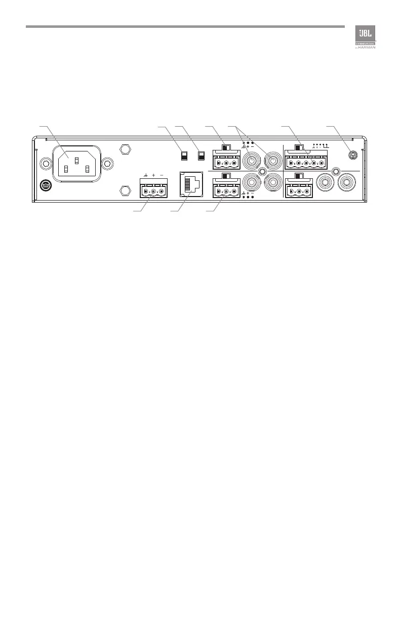
1.3 Rear Panel Controls and Connectors - Four Channel
A. AC Power Inlet – Detachable IEC
B. 70Hz HPF Switch - Activates this function to allow frequencies above 70Hz
pass through and reduce signals with lower frequency.
C. Phantom Power Switch - Applies 27V phantom power source for
microphones.
D. Mic/Line Selection Switch - Allows user to select the gain depending upon
the source used.
E. Dual RCA Input Connector - Stereo, unbalanced sources will be summed
together. (Ch2-4)
F. Priority Input Connector - 5-pin Euro-block includes 3 pins for a balanced
input as well as two pins that, when shortened together, activates the
priority function. (Ch1)
G. VOX Adjustment - allows the input level to be set that will invoke priority
override. (Ch1)
H. Line Level Output Connector
I. Remote Volume connector – RJ45 style connector to connect to a JBL
CSR-V control module.
J. Mic/Line Input Connector - 3-pin Euro-block connector, balanced input (Ch
2-4)
Figure 1.3 Rear View - CSM 14
100-240 V~ 50/60Hz 6W
MADE IN MALAYSIA
CAUTION - TO REDUCE THE RISK OF ELECTRIC
SHOCK, GROUNDING OF THE CENTER PIN OF
THE PLUG MUST BE MAINTAINED.
5040055
CSM 14
OUT
PHANTOM
70HZ
HPF
CSR-V ONLY
CH2 INPUT
MICLINE
CH1 INPUT
MICLINE
PRIORITY
VOX
CH3 INPUT
MICLINE
CH4 INPUT
MICLINE
MONO SUM MONO SUM
MONO SUM
A C D F GE
B
H I J