22
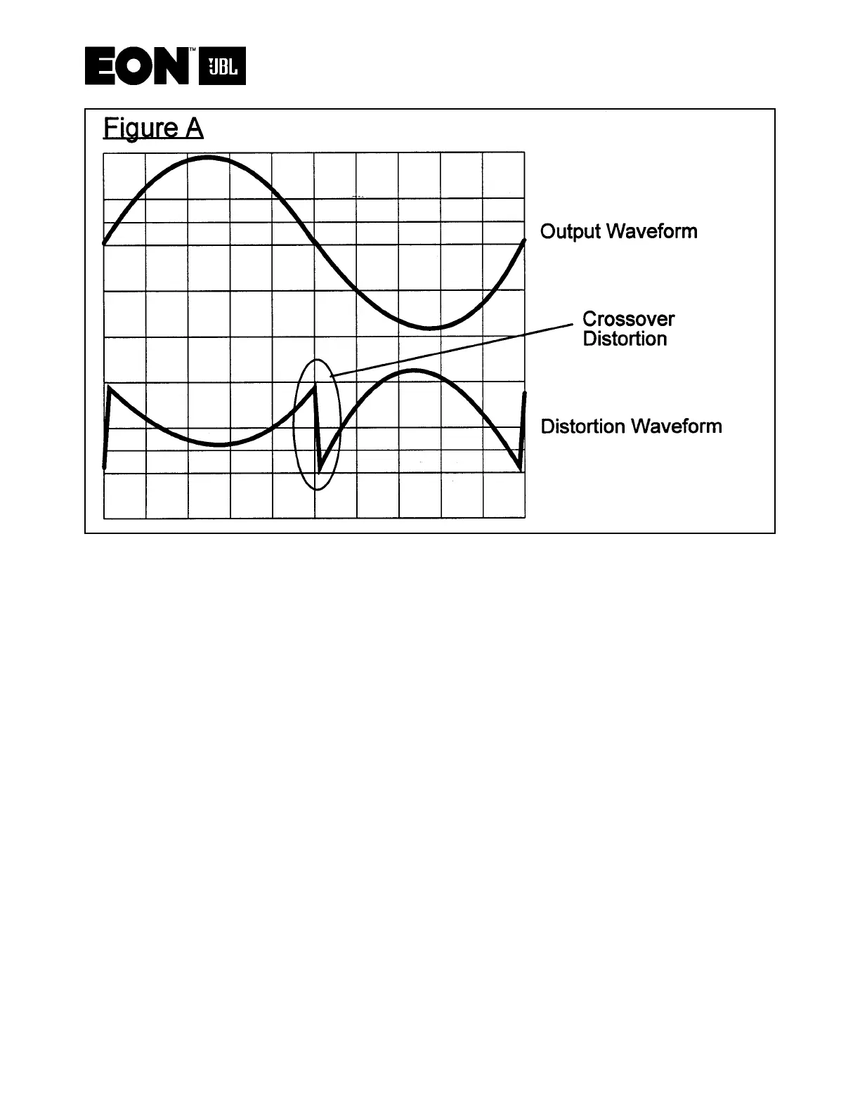
4. Crossover distortion in output
Refer to Figure A above and note the character of crossover distortion. This is caused by
both halves of the output stage (Q1, Q2 on positive side, and Q13, Q12 on the negative
side) being turned off right around crossover (crossover from positive drive to negative
drive). This actually takes a small chunk (sometimes only visible in distortion waveform)
out of the center of the output waveform. This also causes some harmonic distortion (Note
the curved portions of the “Distortion Waveform”). Remove input signal to amp and mea-
sure DC voltage across emitters of Q1 and Q13. Bias adjustment, VR1, should allow
adjustment from zero volts to well over 10mV. If not proceed to “Bias Reference Test”.
 Loading...