CONNECTING
THE PARAGON
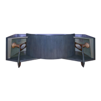
The curved refractor panel can now be set into place.
This is most easily accomplished by two persons. Lower the
panel from the top of the enclosure, sliding the edges through
the notches at the ends of the curved cabinet sections. Take
care to avoid scratching the surface of the midrange horns.
When correctly positioned, the panel fits tightly and butts
firmly against the top of the enclosure.
IMPORTANT: When connecting or disconnecting loud
speakers from an amplifier, the amplifier must be turned
off. Making connections while the amplifier is operating
could seriously damage the loudspeaker system and void the
warranty.
For loudspeaker connections up to 15 m (50 ft) from the
amplifier, 1 mm (#18 AWG) insulated wire (ordinary house
hold lamp cord) is the minimum size recommended. Beyond
this distance, heavier wire is desirable: 1.3 mm (#16 AWG)
to 30 m (100 ft), and 1.6 mm (#14 AWG) to 60 m (200 ft). If
lampcord is used, wires can be differentiated by noting that
one of the insulating jackets is smooth, while the other has a
distinct ridge. By considering the ridged jacked “red” and the
smooth jacket "black,” wiring connections can be made as if
using color-coded wire.
Connections to the audio power source are made using the
four pushbutton terminal posts located on the back of the
Paragon enclosure. The holes in JBL terminal posts do not
allow the connecting wire to pass all the way through, pre
venting the possibility of a short to the other terminal post
or to nearby electrical conductors.
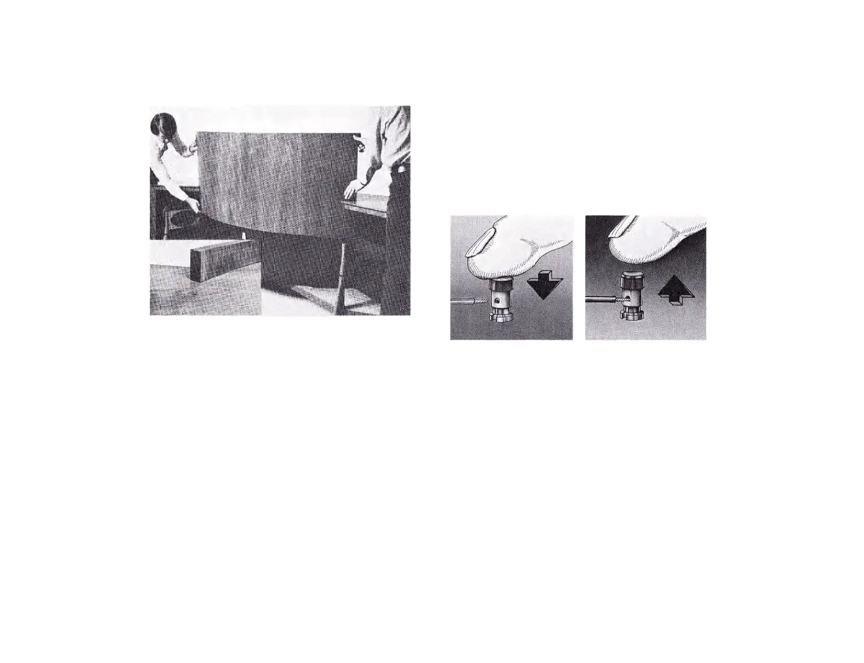
To make a secure connection, strip approximately 1/4
inch of the insulation from the end of the wire, push down
the spring-loaded terminal post cap, insert the bare wire into
the exposed opening of the terminal post and release. (Inser
tion of the wire into the opening will be easier if the stripped
4
wire is first tinned with a soldering tool and solder.)
Locate the loudspeaker output terminals on the back of
the receiver or power amplifier. For each loudspeaker sys
tem, connect the wire from the black terminal post to the
amplifier output terminal labeled “common/ "ground” or
( —), and the wire from the red terminal post to the re
maining 8-ohm speaker output.
Note that many amplifiers have a chassis grounding
terminal which is usually isolated from the other connec
tors. This should not be confused with the "ground”
designation sometimes used to describe two of the terminals
in each set of loudspeaker connections.
The specified 8-ohm impedance rating is a nominal figure
which suggests a connection giving the most efficient power
transfer between amplifier and loudspeaker system. How
ever, 4- or 16-ohm amplifier terminals can be used without
danger.
1. Depress colored button, exposing hole in terminal post.
2. Push stripped end of lead wire into hole and release button.
Never apply twisting force to the terminal post.
Under most conditions, the three position switch on each
midrange dividing network (LX5) should be placed in the
MED (medium) position. The continuously variable control
on the high frequency dividing networks (N7000) should be
rotated until the number four on the control knob is at
approximately the "12 o’clock" position. This is considered
the normal position: with the controls set in this manner, a
smooth tonal balance will be heard in the majority of
listening rooms. However, in rooms that are either
excessively reverberant or excessively "dead” acoustically,
alternate settings of the network controls may be required.
Of course, even though the acoustics of a room may be
ideal, personal listening preferences vary as do the sound
characteristics of different types of playback equipment.
Either of these general conditions may suggest settings other
than those originally described.
Whether compensating for room acoustics or changing to
suit personal listening preferences, the procedure for the
initial balancing of the system is the'same. Prior to changing
the network settings, audition several selections from
ADjUSTINGTHE SYSTEM
5