Do you have a question about the JBL PSW-D110 and is the answer not in the manual?
Identifies components requiring special attention for safety.
Procedure to test unit safety before customer return.
Lists parts that must be replaced with exact equivalents.
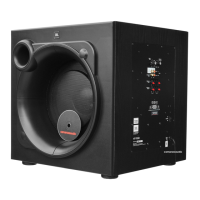
Indicator light status based on signal presence and power.
Adjusts the subwoofer's volume relative to the system.
Sets the roll-off point for the highest frequencies the subwoofer produces.
Selects between in-phase or 180-degree out-of-phase output.
Sets the roll-off point for the lowest frequencies produced at the High Pass Output.
Outputs for powering main speakers with a high-pass filter.
Preferred main input connection for the subwoofer.
Alternative input for when line-level is unavailable or for specific setups.
Outputs for main loudspeakers when using speaker inputs.
Explains how to set High-Pass and Low-Pass crossover controls.
Guides on adjusting the phase switch for optimal bass output.
Connecting without subwoofer/preamp outputs.
Connecting with subwoofer/preamp outputs.
Connecting with preamp outputs and separate amp.
Checks for no sound when using speaker inputs.
Checks for issues resulting in low bass output.
Checks for no sound when using line inputs.
Procedures for basic functional testing of the unit.
Testing the unit's response across a frequency range.
Procedures for testing the woofer driver's performance.
Procedures for testing the amplifier module's electrical parameters.
Procedures for testing the pre-amplifier circuitry and inputs.
Instructions on safely removing the subwoofer grille without damage.
Procedure to check and re-solder critical joints for common failures.
Addresses 'no output' complaints due to damaged capacitor C6.
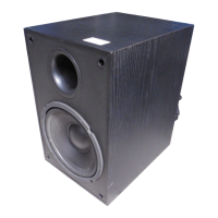
Exploded view of the DPS-10 subwoofer cabinet components.
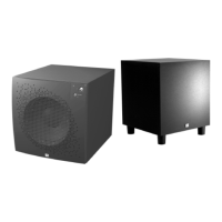
Exploded view of the PSW-D110 subwoofer cabinet components.
Lists mechanical parts unique to the DPS-10 model.
Lists mechanical parts unique to the PSW-D110 model.
Exploded view of packaging components for the DPS-10.
Exploded view of packaging components for the PSW-D110.
Component placement diagram for PCB revision 3.53.
Solder side trace layer diagram for PCB revision 3.53.
Component placement diagram for PCB revision 3.93.
Solder side trace layer diagram for PCB revision 3.93.
Lists resistor and capacitor part numbers and values.
Lists diodes, transistors, and integrated circuit components.
Lists inductors, fuses, and other miscellaneous parts.
Safety precautions for installing the power amp module.
Pinout and description for the LM324 Quad Op Amp.
Pinout and description for the TLO 82 Dual Op Amps.
Diagrams and descriptions for PNP and NPN transistors used.
| power output (RMS) | 150 watts |
|---|
| driver size | 10" |
|---|---|
| driver material | High-Polymer Laminate |
| inputs | Line Level and Speaker Level |
|---|---|
| outputs | Line Level and Speaker Level |
| frequency range | 60Hz – 180Hz |
|---|---|
| frequency response | 30Hz – low-pass crossover setting |
| dimensions | 15-3/8 x 15-3/8 x 17" / 391 x 391 x 432mm |
|---|---|
| weight | 33 lbs / 15 kg |