Do you have a question about the JBL Sub 6 and is the answer not in the manual?
Detailed technical specifications for the JBL Sub6 model.
Detailed technical specifications for the JBL Sub10 model.
Highlights of the Sub6 and Sub10 powered subwoofers.
Step-by-step guide for taking apart the Sub6/10 subwoofer.
Explanation of the front and rear control panel functions.
Equipment and procedures for testing the powered subwoofer.
Visual representation of the subwoofer's internal signal flow.
Diagram showing all parts of the Sub6/10 subwoofer disassembled.
List of mechanical components for the Sub6 model.
List of electrical components for the Sub6 model.
Detailed list of resistors, diodes, transistors, and ICs for the Sub6.
List of miscellaneous components for the Sub6 model.
List of mechanical components for the Sub10 model.
List of electrical components for the Sub10 model.
Detailed list of resistors, diodes, and transistors for the Sub10.
List of ICs and miscellaneous parts for the Sub10.
Illustration of how the Sub6 and Sub10 subwoofers are packaged.
Layouts for the input and connector printed circuit boards.
Layout for the main amplifier printed circuit board.
Layouts for phase switch and control printed circuit boards.
Circuit diagrams for BA4558, TL074CN, and UPC1298V integrated circuits.
Circuit diagrams for MC78L15 and MC79L15 integrated circuits.
Pinout diagrams for various transistors used in the subwoofer.
Wiring schematic for the JBL Sub6 powered subwoofer.
Wiring schematic for the JBL Sub10 powered subwoofer.
Complete circuit schematic for the JBL Sub-6/Sub-10.
Further details and sections of the Sub6/Sub10 circuit schematic.
Final sections of the Sub6/Sub10 circuit schematic.
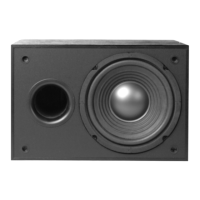
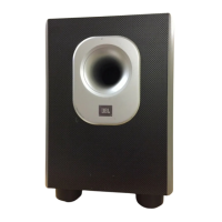
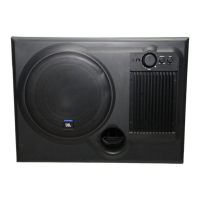
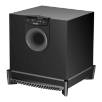
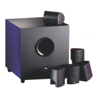
The JBL Sub 6/10 is a powered subwoofer designed to enhance the low-frequency output of an audio system. It comes in two models, Sub6 and Sub10, which share identical controls and many features, differing primarily in woofer size, amplifier power, and physical dimensions.
The subwoofer integrates an amplifier, crossover, and speaker into a single enclosure. It processes audio signals to reproduce bass frequencies, offloading this task from main speakers and allowing them to focus on mid-range and high frequencies. This results in a more balanced and impactful sound experience.
Key functional blocks include:
The subwoofer features an Auto Turn-On/Off Circuit. When the Volume knob is turned clockwise to ON, the LED lights green. If the Volume knob is turned fully counterclockwise (OFF) or the receiver/amplifier has been off for five minutes, the LED lights red, and the subwoofer enters standby. It will automatically turn on again when an audio signal is detected from the receiver/amplifier.
The Sub 6/10 series offers two distinct models with varying performance capabilities:
The JBL Sub 6/10 offers several user-friendly features for integration into various audio setups:
The service manual outlines detailed disassembly and testing procedures for maintenance and repair:
The manual also provides detailed part lists for both mechanical and electrical components, including capacitors, resistors, diodes, transistors, and integrated circuits, which are essential for identifying and replacing faulty parts during repair. Exploded assembly views and wiring diagrams further aid in understanding the internal layout and connections, facilitating troubleshooting and repair.