-
11
-
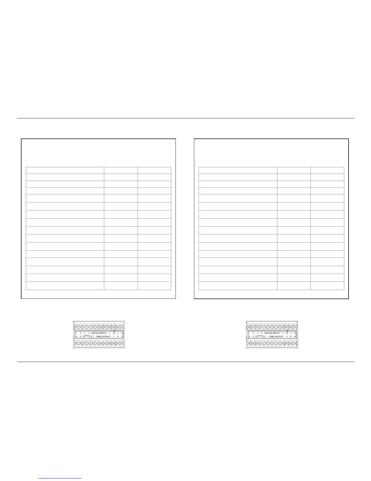
Input/Output AssignmentsJBL SYNTHESIS SDEC-5500
Below shows the SDEC-4500X connections for both factory and alternate settings when used
with the SDEC-5500
SDEC 4500X with SDEC 5500
(Factory Setting)
Standard
IC
Cable #
Output
Connections
Left Front-Low / Full Range 1 A1
Left Front -Hi (n/c Full Range) 2 A2
Right Front -Low / Full Range 3 A3
Right Front -Hi (n/c Full Range) 4 A4
Center Front -Low /Full Range 5 B1
Center Front -Hi (n/c Full Range) 6 B2
Side Left 7 B3
Side Right 9 B4
CH9 9 C1
CH10 10 C2
CH11 (CH15) 11 C3
CH12 (CH16) 12 C4
Rear Left 13 D1
Rear Right 14 D2
CH13 15 D3
CH14 16 D4
Alt Output SDEC 4500X with SDEC 5500
(Alternate Setting)
Alternate Output
IC
Cable #
Output
Connections
Left Front-Low / Full Range 1 A1
Left Front -Hi (n/c Full Range) 2 A2
Right Front -Low / Full Range 3 A3
Right Front -Hi (n/c Full Range) 4 A4
Center Front -Low /Full Range 5 B1
Center Front -Hi (n/c Full Range) 6 B2
Side Left 7 B3
Side Right 9 B4
CH9 9 C1
CH10 10 C2
Rear Left 11 C3
Rear Right 12 C4
Subwoofer 1 13 D1
Subwoofer 2 14 D2
Subwoofer 3 15 D3
Subwoofer 4 16 D4
Factory Setting: With the SDEC powered up and running, connect Control Input C11 to “C”.
This is a temporary connection and should not be left in place.
Alternate Setting: With the SDEC powered up and running, connect Control Input C12 to “C”
(common) on the back of the unit. This is a temporary contact and should not be left in place.
 Loading...