VT X A12 | User Manual
25
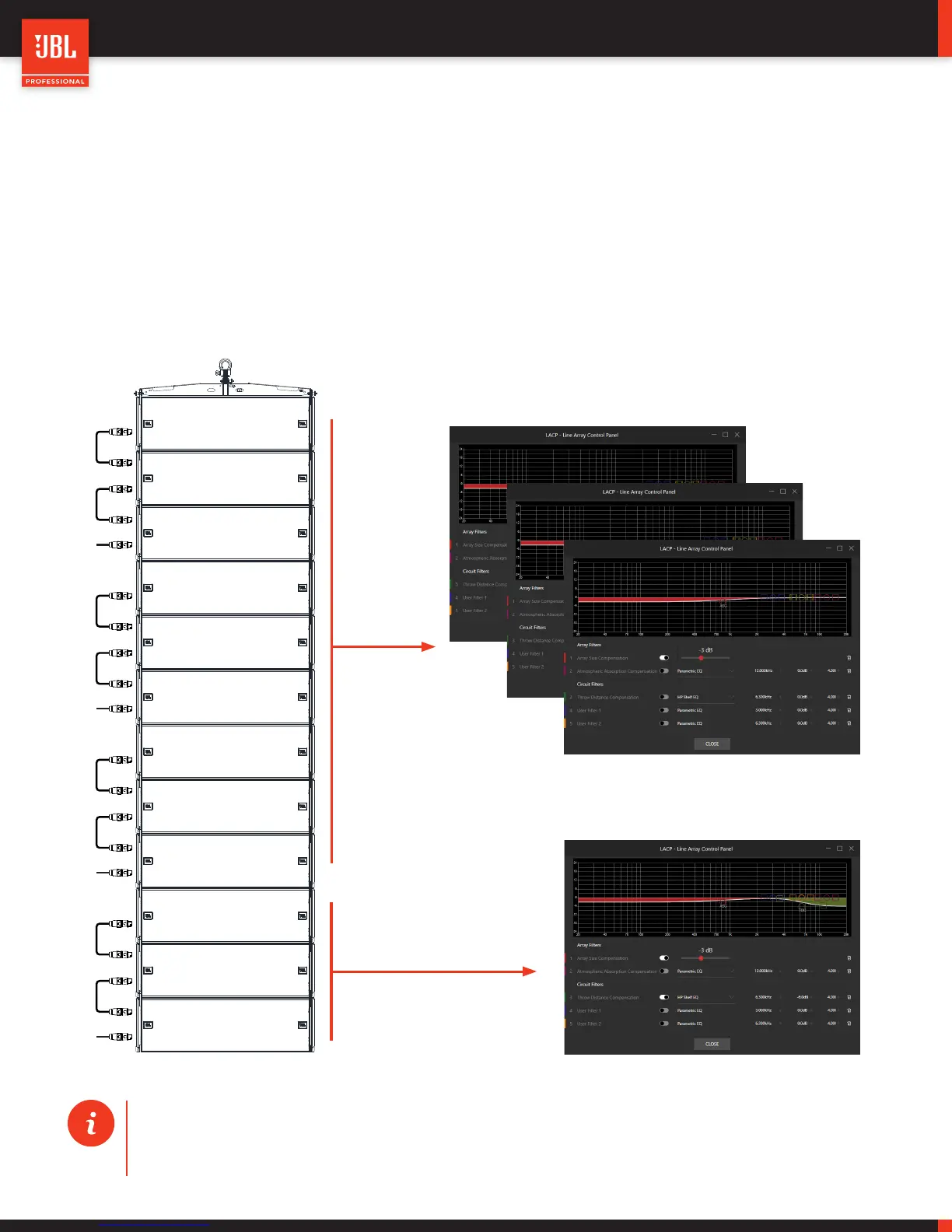
11.6 - EXAMPLE USING LACP
This example is for a 12-cabinet VTX A12 array. The standard A12 preset is used with the Array Size Compensation
filter set to –3dB to offset LF buildup and achieve a flatter frequency response. As seen from the illustration below,
Array Size Compensation is globally applied to all array circuits. The bottom circuit includes some HF attenuation using
HF Throw Distance Compensation (Filter 3) to correct for proximity differences. Using some simple adjustments to the
LACP filters will get an A12 system to a very good staring point. Any further required adjustments will be dependent
upon the room and specific application.
TIP: The LACP parameters used in LAC to predict an array can be easily applied to an actual array in Perfor-
mance Manager. For information on how to import LACP parameters in Performance Manager, please refer
to the Performance Manager documentation.