51 - 4
Drive Head Maxtrac - Assembly (cont'd)
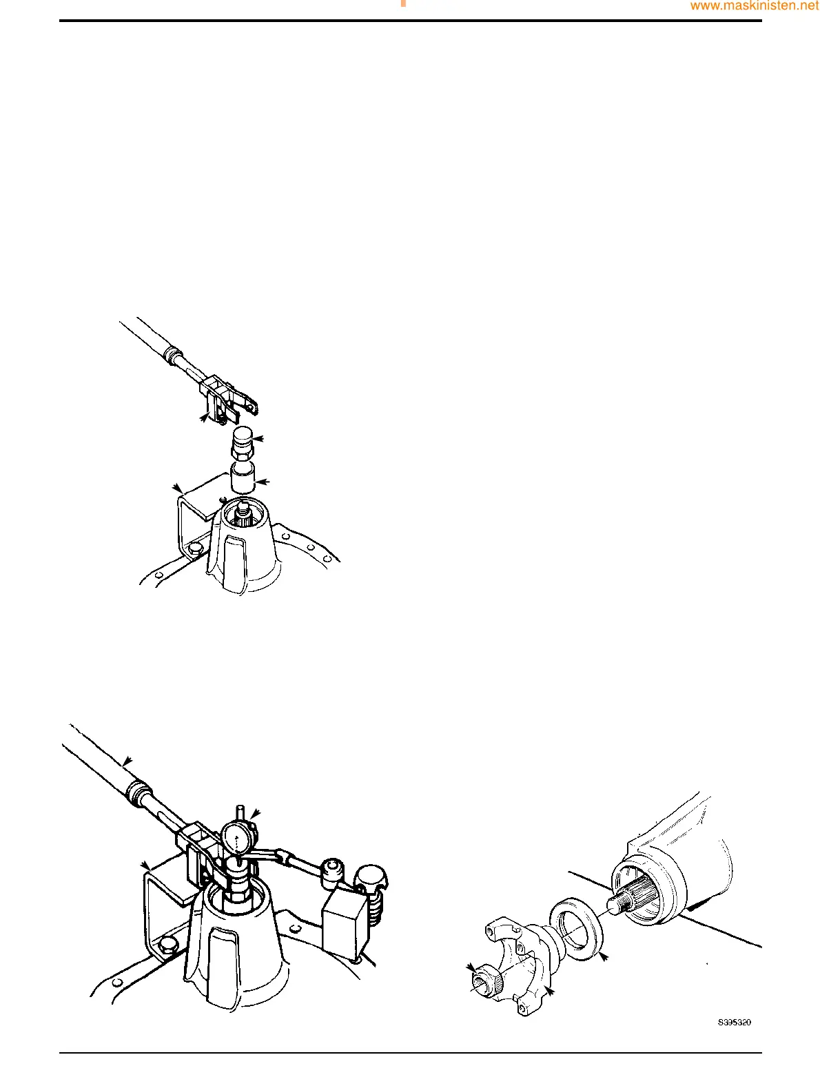
14 Fit special tool sleeve B and special pinion shaft
adapter C. Tighten adapter C to approximately 50 Nm,
making sure the pinion is free to rotate and there is end
float, this will prevent any damage to the bearing. If the
pinion is not free to rotate or there is no end float at this
stage check the bearing is fitted correctly. Also check
the correct size spacer has been fitted.
15 Fit special bracket D to the drive-head housing using
two M10 x 30 nuts and bolts. Fit special tool support
pillar E to bracket D so that the fork end engages in
adapter C. Ensure that fork E is centrally located on
adapter C. If necessary, re-align bracket D to suit.
16 Fit dial test indicator (DTI) F. Ensure that the DTI is
mounted on the drive head and not on bracket D.
17 Set torque wrench G to 35 Nm (25.8 lbf ft) and measure
the end float while rotating the shaft.
Section F Transmission
9803/7130
Section F
51 - 4
Issue 1
Rear Axle
18 To select the right size solid spacer, subtract the end
float obtained at step 17 from the solid spacer size
(14.20 mm). Also subtract 0.04 mm to allow for
theoretical bearing tolerance and pre load. The result is
the size of spacer to be fitted from the solid spacer
setting kit. If there is no spacer of this size, fit the next
nearest size spacer, refer to Service Tools - Axles.
Example
Temporary spacer size 14.20
Subtract end-float 0.25
Total 13.95
Subtract tolerance & preload 0.04
Result 13.91
(No spacer available this size, use next nearest size
spacer i.e 13.900)
19 Remove sleeve B and temporary spacer. fit correct size
spacer from solid spacer setting kit, refer to Service
Tools - Axles. During removal take care to avoid
damaging the outer bearing.
20 Fit sleeve B. Tighten adapter C to no more than 50 Nm
to protect against bearing damage while spacer
selection is verified making sure the pinion is free to
rotate. Check there is no end float and pinion is free to
turn smoothly by hand. Remove adapter C and fit stake
nut K. Then check that rolling torque is less than 2.0
Nm. If the rolling torque exceeds 2.0 Nm, check that the
shaft has been assembled correctly.
Note: If the pinion is not free to rotate check the correct size
spacer has been fitted.
21 If rolling torque measured at step 20 is too high, fit the
next larger size spacer. If rolling torque is too low, fit the
next smallest size spacer. If a correct spacer is not
available from the range, check that drive head is
assembled correctly.
22 Remove adapter C and sleeve B.
23 Fit new oil seal H, grease between seal lips before
fitting. Fit coupling yoke J and NEW stake nut K.
FF
GG
348040
CC
BB
DD
348030
EE
DD
KK
HH
JJ