Dismantling (cont’d)
23 Place the travel motor horizontally, taking care to collect
any oil left inside.
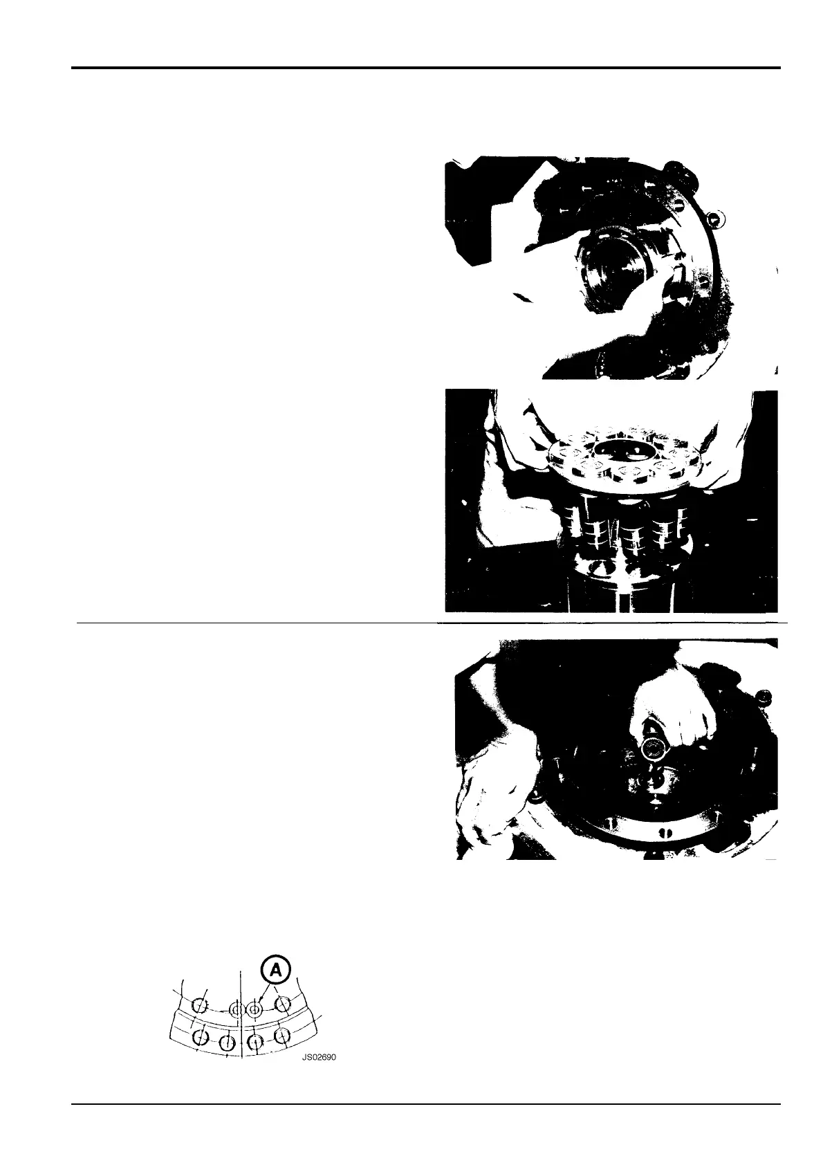
Holding the cylinder block 104 with both hands, rotate it
to the right and left two or three times in order to
separate shoes 106 from swash plate 103.
Note: Failure to do this could cause piston parts to stick to
the swash plate and fall into the spindle.
Remove cylinder block 104, plates 116, friction plates
115, and plate 169 from spindle 2.
Remove the piston assembly comprising pistons 105,
shoes 106, retainer plate 107, thrust bowl 108, washer
111 (JS160 only) and pins 151 from cylinder block 104.
Note: Hydraulic motor shaft 102, bearing 149 and oil seal
132 cannot be removed from this side of the reduction gear.
If it is necessary to remove these components refer to
Reduction Gear, Dismantling.
24 Remove the swash plate 103/thrust plate 153 (JS130
only) assembly, the two steel balls 167 (pivots 167 on
JS160) and the 2-speed switch piston assembly (piston
161, shoe 162, spring 179 (191 on JS160) out of spindle
2. Separate the swash plate and thrust plate by prying
apart (JS130 only).
Note: Piston 161 and shoe 162 are a matched set. If either
shows signs of wear or damage, renew both as a set.
Note: Remove 2-speed control piston assembly, comprising
piston 161, shoe 162 and spring 191, by applying
compressed air to port A spindle 2.
! CAUTION
When using compressed air, wear safety glasses and
gloves. Do not direct compressed air at your skin.
8-3-4-2
8 - 8
Section F Transmission
9803/6410
Section F
8 - 8
Issue 1
Traction Motor