41 - 7
Assembly (continued)
3. Tighten the hexagonal socket head bolts (125) to the
specified torque. (300 kgf-cm).
Note: Tighten the bolts alternately a little at a time until they
are tightened to the specified torque.
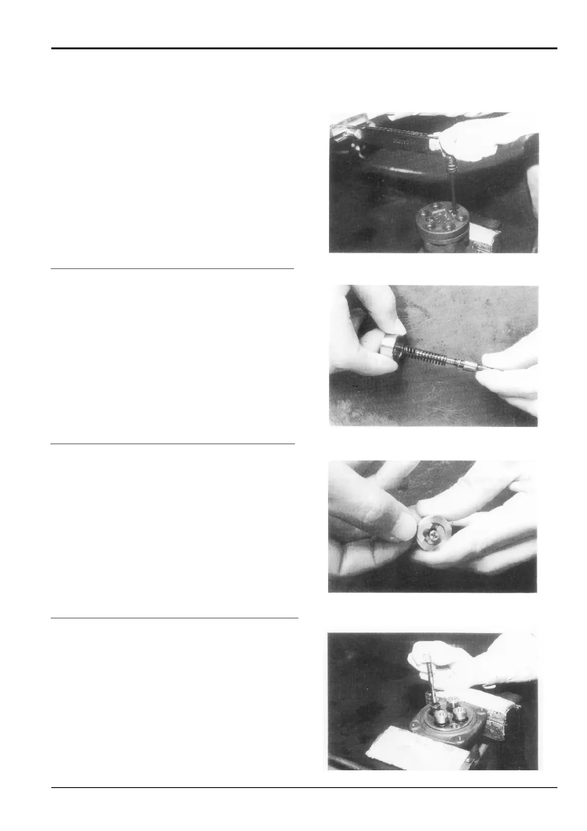
4. Mount the washers 2 (217), springs (241) and spring
seats (216) in order onto the spools (201).
5. Stand each spool (201) on a level work bench, push the
spring seat up and insert the two semicircular washers 1
(215) into the top of the spring seat, such that they do
not overlap.
Note: Install the washer 1 (215) so that its sharp edge side
catches on the spool head.
Do not pull down the spring seat by more than 6 mm.
6. Mount the spring (221) into the case.
Mount the pressure reduction assembly into the casing.
Note: Assemble them in the original positions before
assembly.
Section E
Hydraulics
9803/6400
Section E
41 - 7
Issue 1
Remote Control Valve JS200/JS240