7 - 12
Assembly (continued)
11. Assemble (30) (31) ‘O’-rings which have been greased
into (25) brake piston.
Assemble the (25) brake piston into the (1) case.
Align so that the two pinholes of the (25) brake piston
and the two pinholes of the (1) are aligned in a
straight line.
12. Place the jig for aligning the brake piston and lightly
tap the head of the jig with plastic hammer evenly
and insert the (25) brake piston.
13. Assemble the (22) (33) ‘O’-rings in the (1) case.
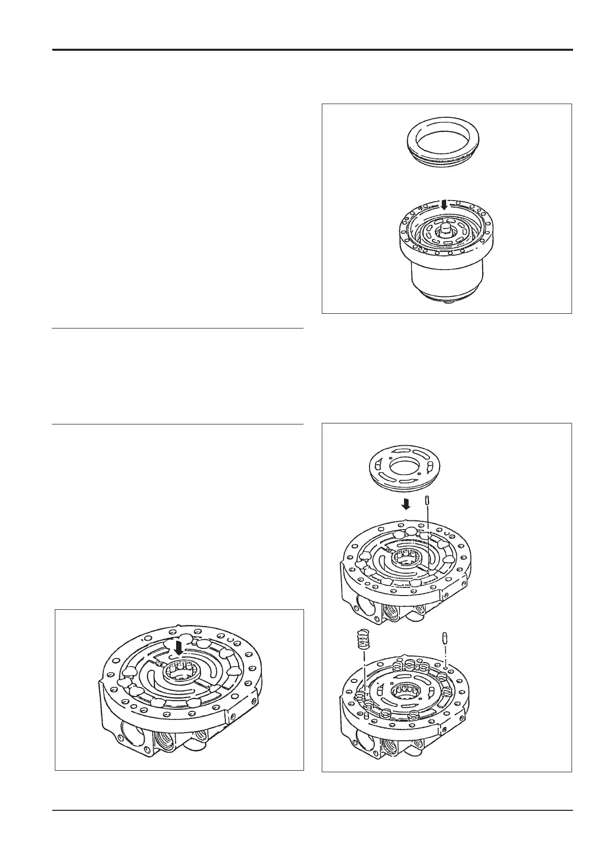
14. Fix the (2-1) base plate on the work bench and
assemble the (13) ball bearing, (28) four pins, (18)
pin, (5) valve plate and (29) (41) springs.
Note: Apply grease to the non-sliding areas of the valve
plate and base plate.
Be careful not to damage the sliding area of the valve plate.
To prevent the springs from falling, coat them with grease.
Section F
Transmission
9803/6400
Section F
7 - 12
Issue 2*
Motor
*