Part No. 960-100932R_Rev. A © 2014, JCM American, Corporation Part No. 960-100932R_Rev. A © 2014, JCM American, Corporation
iVIZION® Banknote Validator Operator’s Guide Operator’s Guide June, 2014
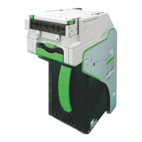
CLEANING THE TRANSPORT (MONTHLY/12,000 CYCLES)
1. Open the Rear Transport Cover on the Transport Unit. To do so, pull forward on
the green release catch on the top of the Transport Unit, to expose the rear section
of the Transport Unit for cleaning (refer to
Figure 3).
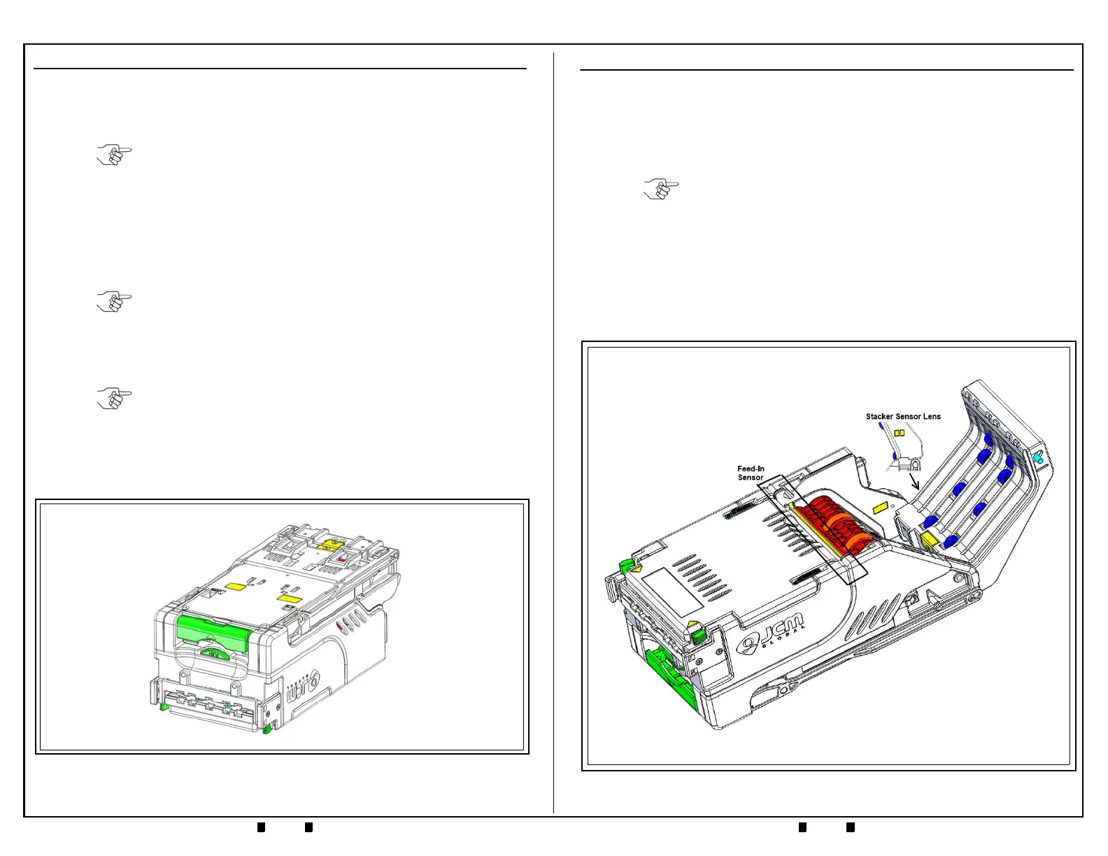
2. Use a clean, lint-free Micro-Fiber cloth (dampened with cleaning solution) to
wipe off any dirt and stains from the Optical Sensors (refer to the yellow areas in
Figure 3).
3. Locate the Feed-In Optical Sensor Lenses, directly in front of the Anti-Stringing
Mechanism (refer to the red areas in
Figure 3). This area features a grooved
channel in the molding that can collect dust in dirty environments.
4. Use a clean, lint-free Micro-Fiber cloth to wipe the grooved channel clean, and
reduce the risk of false “Bill Jam” errors.
5. Using a clean, lint-free Micro-Fiber cloth (dampened with cleaning solution),
clean and dry the Feed-In Optical Sensor Lenses located on each side of the
Transport Path.
NOTE: Be sure to wipe down the entire Bill Path in both the upper and lower
sections of the Transport Unit.
Figure 3 iVIZION Transport Unit
CLEANING THE TRANSPORT (ANNUAL/144,000 CYCLES)
1. Perform the Monthly Transport Cleaning Procedures (refer to Page 5).
2. Perform the 6 Month Transport Cleaning Procedures (refer to Page 9).
3. Use the JCM Tool Suite application to run the Aging Test. Listen for excessive or
unusual noise.
4. The Transport Unit uses light pipes for the transfer of some optical signals in the
unit. Remove the bottom cover of the Transport Unit to clean the Lenses on the
inside of the Transport Cover where these signals cross over (refer to
Figure 8,
yellow areas).
5. Clean the Sensor components on the Processor PCB, using compressed air or
moisture-free low pressure (LP) air to blow out any dust.
6. Remove the Motor Gear Assembly.
7. Remove the Encoder PCB from the Motor Gear Assembly.
8. Use compressed air or moisture-free low pressure (LP) air to blow out any dust or
debris from the gears.
9. Inspect the Motor Drive Gear Assembly for damaged or worn gears.
10. Reinstall the Motor Drive Gear Assembly in the Transport Unit, and then reinstall
the bottom cover.
11. Use a clean, dry, lint-free Microfiber cloth to wipe down the Transport Unit and
remove any cleaning solution, moisture or residue that may remain on the Optical
Sensor Lenses.
NOTE: Perform at least 5 Aging Cycles. If necessary, replace the Motor Gear
Assembly.
NOTE: Refer to Section 4 of the iVIZION Operation and Maintenance Manual
(JCM P/N 960-100929R) for removal instructions.
NOTE: If necessary, replace the Motor Drive Gear Assembly.
Figure 8 iVIZION Transport Unit (Inverted)

 Loading...